Ten moduł steruje klimakonwektorami z doprowadzeniem świeżego powietrza, powszechnie stosowanymi w budynkach komercyjnych i hotelach.
W zależności od aktualnej temperatury w pomieszczeniu (ϑc), temperatury zadanej (ϑt) oraz poziomu CO2 (CO2) regulowana jest ilość powietrza oraz praca zaworów.
Regulacja zależy od stanu pracy i jest realizowana za pomocą regulatora PI na podstawie temperatury lub jakości powietrza.
Spis treści
Wejścia↑
| Skrót | Krótki opis | Opis | Jednostka | Zakres wartości |
|---|---|---|---|---|
| ϑc | Current Room Temperature | Wartość zostanie dostarczona przez podłączony inteligentny regulator pomieszczeniowy. Jeśli wykorzystywane jest również dane wejściowe, zastosowana zostanie ostatnia zmiana. | ° | ∞ |
| ϑt | Target Room Temperature | Wartość zostanie dostarczona przez podłączony inteligentny regulator pomieszczeniowy. Jeśli wykorzystywane jest również dane wejściowe, zastosowana zostanie ostatnia zmiana. | ° | ∞ |
| Ha | Heating Available | Potwierdzenie dostępności energii grzewczej w tym urządzeniu. Można stosować samodzielnie (np. stan „gotowości” pompy ciepła, włączenie kotła) lub w połączeniu z centralnym sterownikiem Fan Coil jako lokalną kontrolę, czy ciepła woda dotarła do urządzenia (zabezpieczenie oparte na czasie przepływu). PRAWDA / brak połączenia: ogrzewanie może działać na żądanie. FAŁSZ: moc grzewcza jest wymuszona, co zapobiega wdmuchiwaniu zimnego powietrza do pomieszczenia. W przypadku przypisania do centralnego sterownika: połączone operacją AND z informacjami z centralnego sterownika. | - | 0/1 |
| Ca | Cooling Available | Potwierdzenie dostępności energii chłodniczej w tym urządzeniu. Można stosować samodzielnie (np. w trybie „gotowości” agregatu chłodniczego) lub w połączeniu z centralnym sterownikiem Fan Coil jako lokalną kontrolę, czy woda lodowa dotarła do urządzenia (zabezpieczenie oparte na czasie przepływu). PRAWDA / brak połączenia: chłodzenie może działać na żądanie. FAŁSZ: moc chłodnicza jest wymuszona na wyłączenie, co zapobiega wdmuchiwaniu ciepłego powietrza do pomieszczenia. W przypadku przypisania do centralnego sterownika: połączenie logiczne AND z informacjami z centralnego sterownika. | - | 0/1 |
| CO2 | Current Room CO2 | Wartość zostanie dostarczona przez podłączony inteligentny regulator pomieszczeniowy. Jeśli wykorzystywane jest również dane wejściowe, zastosowana zostanie ostatnia zmiana. | ppm | 0...∞ |
| Dwc | Door and Window Contact | 0 = Zamknięte 1 = Otwarte | - | 0/1 |
| Rtd | Reset to default | Resetuje parametry i ustawienia bloku do wartości domyślnych określonych w ustawieniu wstępnym bloku. | - | 0/1 |
| Off | Off / Lock | Off / Zablokowane | - | 0/1 |
| Sm | Silent Mode | Po włączeniu maksymalna prędkość wentylatora zostanie ustawiona zgodnie z ustawieniem "Prędkość wentylatora w trybie cichym". Po ponownym wyłączeniu prędkość wentylatora zostanie ponownie obliczona. | - | 0/1 |
| Bm | Boost Mode | Ustawia prędkość wentylatora na maksymalną. | - | 0/1 |
| Pt | Pause Timer | Wstrzymuje urządzenie na czas ustawiony w parametrze (Ptd). | - | 0/1 |
| Fan | Fan Speed | Prędkość wentylatora wyrażona jako procent pełnej mocy. -1 w trybie automatycznym. -1, jeśli nie jest podłączony. | % | -1...100 |
Parametry↑
| Skrót | Krótki opis | Opis | Jednostka | Zakres wartości | Wartość standardowa |
|---|---|---|---|---|---|
| CO2t | Target CO2 | Próg jakości powietrza dla CO₂. Jeśli wartość CO₂ przekroczy ten próg, jakość powietrza uznaje się za złą, a logika działania zmienia się zgodnie z poniższą tabelą. | ppm | 0...∞ | 600 |
| Fmax | Maximum Fan Speed in Auto Mode | Maksymalna prędkość wentylatora w trybie automatycznym | % | 0...100 | 80 |
| Mode | Mode | 0 = Wyłączone 1 = Automatycznie 2 = Ogrzewanie 3 = Chłodzenie 4 = Wentylacja W przypadku ustawienia opcji „Automatycznie” i sterowania za pomocą regulatora pomieszczeniowego, ustawienie zostanie określone przez IRC | - | 0...4 | 1 |
| Ptd | Pause Timer Duration | Rozpoczyna się wraz z narastającym zboczem sygnału wejściowego (Pt). Urządzenie pozostaje w stanie wstrzymania przez określony czas. | s | 0...∞ | 7200 |
| FϑKP | Proportional Gain (Fan Temp) | Współczynnik wzmocnienia proporcjonalnego dla mocy wentylatora w zależności od temperatury. Stosowany w regulatorze PI. | - | 0...∞ | 50 |
| FϑKI | Integral Gain (Fan Temp) | Współczynnik wzmocnienia integralnego dla mocy wentylatora w zależności od temperatury. Stosowany w regulatorze PI. | - | 0...∞ | 0.01 |
| FϑSt | Sample Time (Fan Temp) | Czas próbkowania dla sygnału wyjściowego wentylatora w zależności od temperatury. Stosowany w regulatorze PI. | s | 0...∞ | 60 |
| Fco2KP | Proportional Gain (Fan CO2) | Współczynnik wzmocnienia proporcjonalnego dla mocy wentylatora w zależności od jakości powietrza (CO₂). Stosowany w regulatorze PI. | - | 0...∞ | 50 |
| Fco2KI | Integral Gain (Fan CO2) | Współczynnik wzmocnienia integralnego dla mocy wentylatora w zależności od jakości powietrza (CO₂). Stosowany w regulatorze PI. | - | 0...∞ | 0.01 |
| Fco2St | Sample Time (Fan CO2) | Czas próbkowania dla mocy wentylatora w zależności od jakości powietrza (CO₂). Wykorzystywany w regulatorze PI. | s | 0...∞ | 60 |
| VKP | Proportional Gain (Valve) | Współczynnik wzmocnienia proporcjonalnego dla wyjść zaworowych w zależności od temperatury. Stosowany w regulatorze PI. | - | 0...∞ | 50 |
| VKI | Integral Gain (Valve) | Współczynnik wzmocnienia integralnego dla wyjść zaworowych w zależności od temperatury. Stosowany w regulatorze PI. | - | 0...∞ | 0.01 |
| VSt | Sample Time (Valve) | Czas próbkowania dla wyjść zaworów w zależności od temperatury. Wykorzystywane w regulatorze PI. | s | 0...∞ | 60 |
Wyjścia↑
| Skrót | Krótki opis | Opis | Jednostka | Zakres wartości |
|---|---|---|---|---|
| H | Heating Output | Wyjście ogrzewania | - | 0...10 |
| C | Cooling Output | Wyjście chłodzenia | - | 0...10 |
| HC | Combined Heating/Cooling Output | Wyjście dla zaworów lub siłowników, które mogą ogrzewać i chłodzić | - | 0...10 |
| Fan | Fan Speed Analogue | Analogowa regulacja prędkości wentylatora | - | 0...100 |
| FanS | Fan Speed Step | Aktualny stopień obrotów obliczono na podstawie ustawienia "Stopnie prędkości wentylatora”. | - | 0...∞ |
| ϑc | Current Room Temperature | Aktualna temperatura w pomieszczeniu | ° | ∞ |
| ϑt | Target Room Temperature | Docelowa temperatura w pomieszczeniu | ° | ∞ |
| Mode | Current Mode | 0 = Wyłączone 1 = Automatycznie 2 = Ogrzewanie 3 = Chłodzenie 4 = Wentylacja | - | 0...4 |
| S | Status | Aktywne, gdy którykolwiek z zaworów jest otwarty lub gdy wentylator pracuje. | - | 0/1 |
| API | API Connector | Inteligentny łącznik oparty na interfejsie API. Umożliwia łączenie różnych funkcji między urządzeniami i blokami. Polecenia API | - | - |
Właściwości↑
| Krótki opis | Opis | Jednostka | Zakres wartości | Wartość standardowa |
|---|---|---|---|---|
| Stopnie prędkości wentylatora | Służy do mapowania poszczególnych stopni. Przykład: 4 stopnie → 25% pełnej mocy dla każdego stopnia. Ustawienie wartości 0 wyłącza sygnał wyjściowy Fan Speed Step (FanS). | - | 0...100 | 3 |
| Prędkość wentylatora w trybie cichym | Maksymalna prędkość wentylatora w trybie cichym | % | 0...100 | 10 |
Opis działania↑
Moduł ten reguluje przepływ powietrza oraz moc ogrzewania i chłodzenia w oparciu o aktualną temperaturę, temperaturę docelową oraz jakość powietrza (stężenie CO₂).
Wilgotność nie jest brana pod uwagę.
Ilość powietrza zwiększa się tylko w takim stopniu, w jakim jest to konieczne do utrzymania docelowej temperatury i jakości powietrza, ponieważ większe ilości powietrza powodują większe straty energii.
Wyjścia są sterowane zgodnie z następującą logiką działania:
| Tryb pracy | Objętość powietrza | Wyjście ogrzewania | Wyjście chłodzenia |
|---|---|---|---|
| Ogrzewanie i dobra jakość powietrza | zmienna ϑ | 100 % | 0 % |
| Ogrzewanie i zła jakość powietrza | Zmienna CO₂ | zmienna ϑ | 0 % |
| Chłodzenie i dobra jakość powietrza | zmienna ϑ | 0 % | 100 % |
| Chłodzenie i zła jakość powietrza | Zmienna CO₂ | 0 % | zmienna ϑ |
| Zła jakość powietrza | Zmienna CO₂ | 0 % | 0 % |
| Wszystko w porządku | 0 % | 0 % | 0 % |
Zmienna ϑ
Objętość powietrza jest regulowana w zależności od różnicy między aktualną a docelową temperaturą.
Wyjście ogrzewania lub chłodnicza pracuje z pełną wydajnością.
Zmienna CO2
Ilość powietrza jest regulowana w zależności od jakości powietrza.
W przypadku pogorszenia się jakości powietrza ilość powietrza zostaje zwiększona.
Moc ogrzewania i chłodzenia jest dostosowywana do aktualnego zapotrzebowania.
 | Aby zapewnić stabilną i niezakłóconą regulację, natężenie przepływu powietrza jest dostosowywane raz na minutę, przy czym zmiany są ograniczone do maksymalnie 20%. W rezultacie pełna regulacja od 100% do 0% trwa pięć minut. Na przykład, jeśli jakość powietrza pogorszy się w trybie „Ogrzewanie i dobra jakość powietrza”, regulacja natężenia przepływu powietrza jest stopniowo przełączana z trybu opartego na temperaturze na tryb oparty na stężeniu CO2. |
Przykład programowania↑
Połączenie z inteligentnym regulatorem pomieszczeniowym
Zawory ogrzewania i chłodzenia oraz wentylator są podłączone do odpowiednich wyjść modułu.
Sterownik fancoil z funkcją nawiewu świeżego powietrza można podłączyć do inteligentnego regulatora pomieszczeniowego za pośrednictwem złącza API:
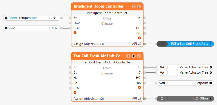
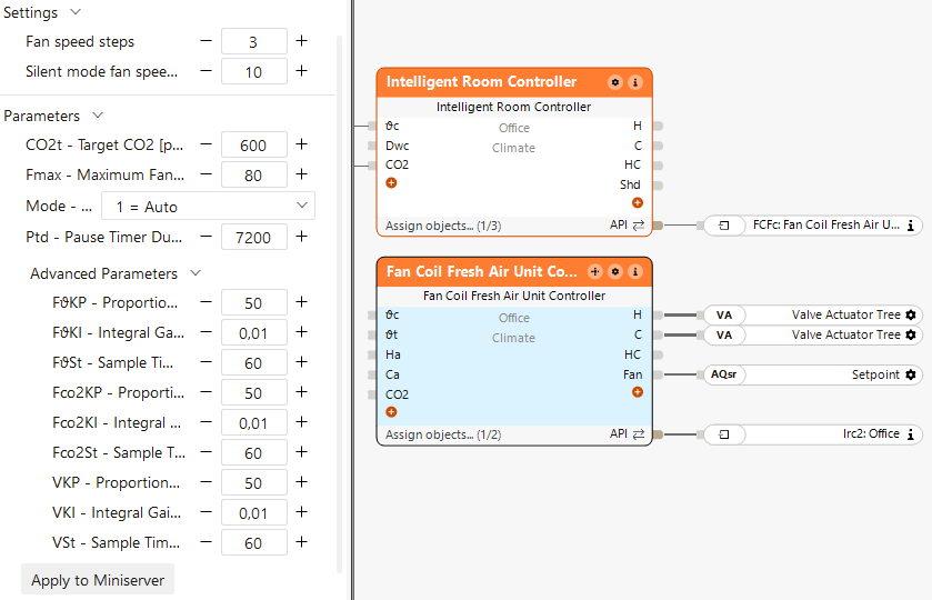
W oknie właściwości można dostosować parametry regulatora PI dla regulacji wentylatora w oparciu o temperaturę, regulacji wentylatora w oparciu o poziom CO₂ oraz regulacji zaworu w oparciu o temperaturę.
Ponieważ w tym przykładzie zastosowano system czterorurowy, nie ma potrzeby łączenia wejść (Ha) i (Ca), ponieważ zakłada się, że ogrzewanie i chłodzenie są dostępne domyślnie.
Inteligentny regulator pomieszczeniowy zarządza logiką pracy pomieszczenia i przekazuje wartości temperatury oraz zapotrzebowanie na ogrzewanie/chłodzenie do regulatora klimakonwektora z funkcją nawiewu świeżego powietrza.
Regulator ten dostosowuje natężenie przepływu powietrza oraz pozycję zaworów ogrzewania/chłodzenia, uwzględniając przy tym jakość powietrza.
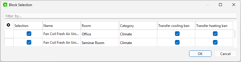
Połączenie z inteligentnym regulatorem pomieszczeniowym i centralnym regulatorem klimakonwektorów
Dwukrotne kliknięcie bloku centralny pozwala dodać odpowiednie sterowniki klimakonwektorów z funkcją nawiewu świeżego powietrza:
W oknie właściwości można bezpośrednio wybrać typ instalacji (2-rurowa lub 4-rurowa):
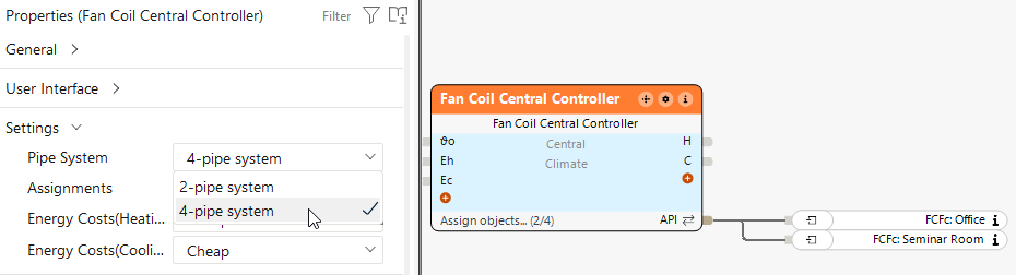
Centralny sterownik klimakonwektorów zbiera sygnały zapotrzebowania i decyduje o wyborze trybu ogrzewania lub chłodzenia.
Na podstawie tej decyzji sterowniki klimakonwektorów z funkcją nawiewu świeżego powietrza regulują położenie zaworów i natężenie przepływu powietrza w poszczególnych pomieszczeniach, uwzględniając jakość powietrza.
Ten blok może również działać samodzielnie. W takim przypadku wartości temperatury i stężenia CO₂ są przekazywane bezpośrednio do bloku poprzez wejścia.