Here you will find instructions on commissioning and additional information.
Step 1: Mounting and connection
Step 2: Intercom Search
Step 3: Set up Intercom Video
Step 4: Create module configuration as network device
Step 5: Set up Intercom Audio
Step 6: Add module configuration to existing network device
Step 7: Change login credentials
Optional – Adding the Door Controller
The SIP settings from this documentation can be followed in a similar way.
Due to the new internal electronics, the product comes with an RJ45 connector instead of an RJ45 socket:
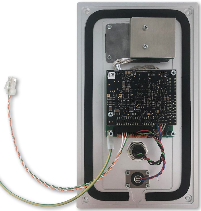
The Intercom XL will not have this change and the product itself is being phased out.
Step 1: Mounting and connection
It is recommended that you mount the intercom with the top edge being 170cm above the ground (67 inches)
- Connect an RJ45 ethernet cable from to your home network to the “Data/LAN In” port of the supplied PoE Injector (PoE = Power over Ethernet).
- Connect an RJ45 ethernet cable from the “Power+Data Out” port of the PoE Injector to the Loxone Intercom.
- Provide power to the POE Injector.
- The recommended maximum length for an ethernet connection is ca. 100m. It is recommended to place the PoE adapter in close proximity to the intercom.
- For ethernet connections of over 100 meters, a different connection must be used, e.g. fibre optic.
- A data rate of 2 MBit minimum is required for adequate audio communication.
- A data rate of 10 MBit is required for adequate video connections.
Step 2: Intercom Search
After the Intercom has been connected to the network and powered on, as described in Step 1, it can then be configured and set up in Loxone Config.
- Open the current document in Loxone Config and connect to the Miniserver.
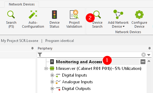
- Click on “Monitoring and Access” in periphery.
- Then select “Device Search” from the top ribbon:
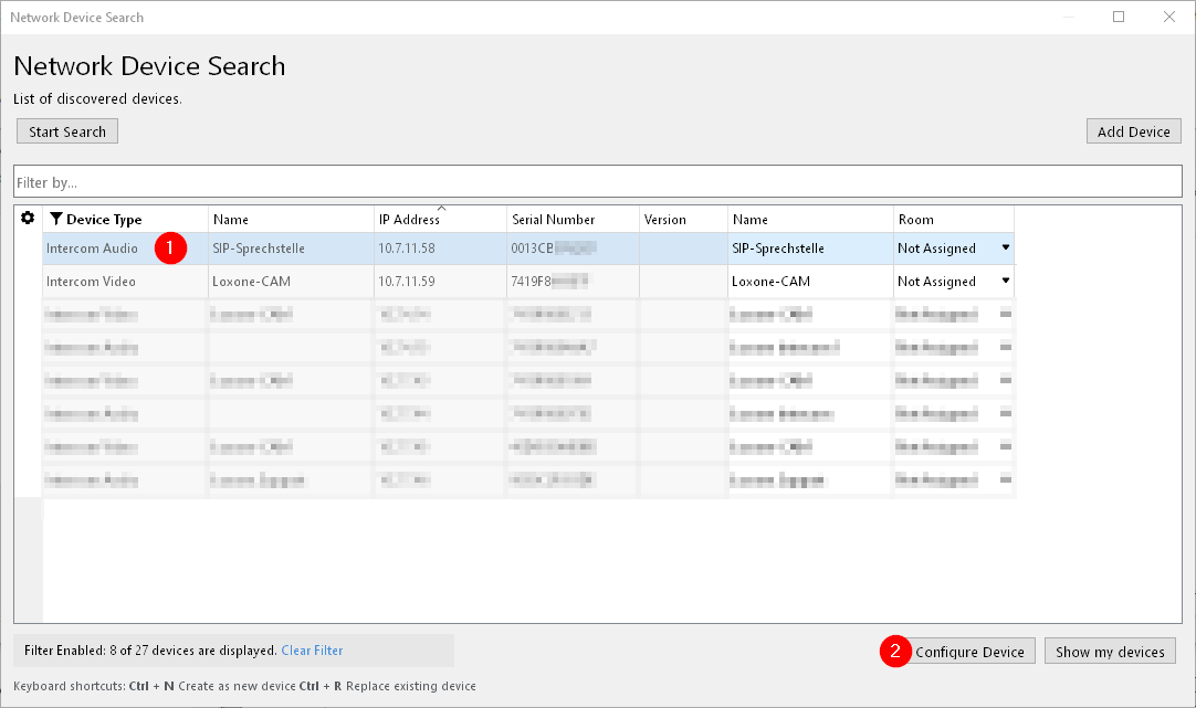
This will open the Network Device Search:
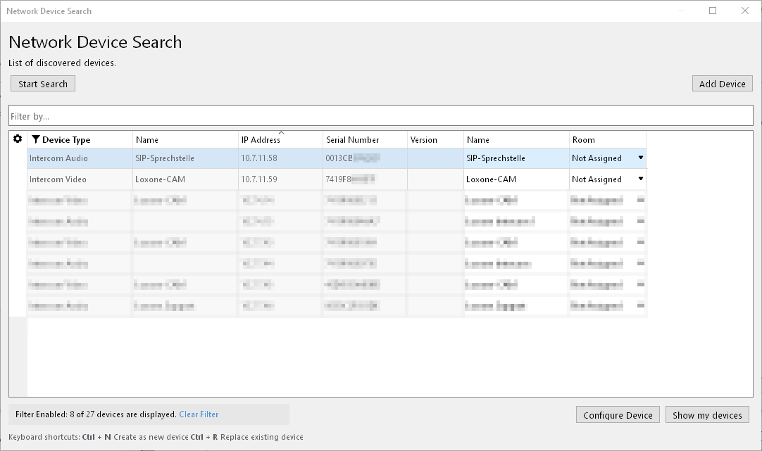
- The search is started automatically, all devices detected by the Miniserver will be displayed. It can take a few minutes until all devices are found.
- The audio module (SIP) and video module (CAM) are listed as two separate entries.
- The modules are configured in two separate steps. (video in Step 3 and audio in Step 5)
Step 3: Set up Intercom Video
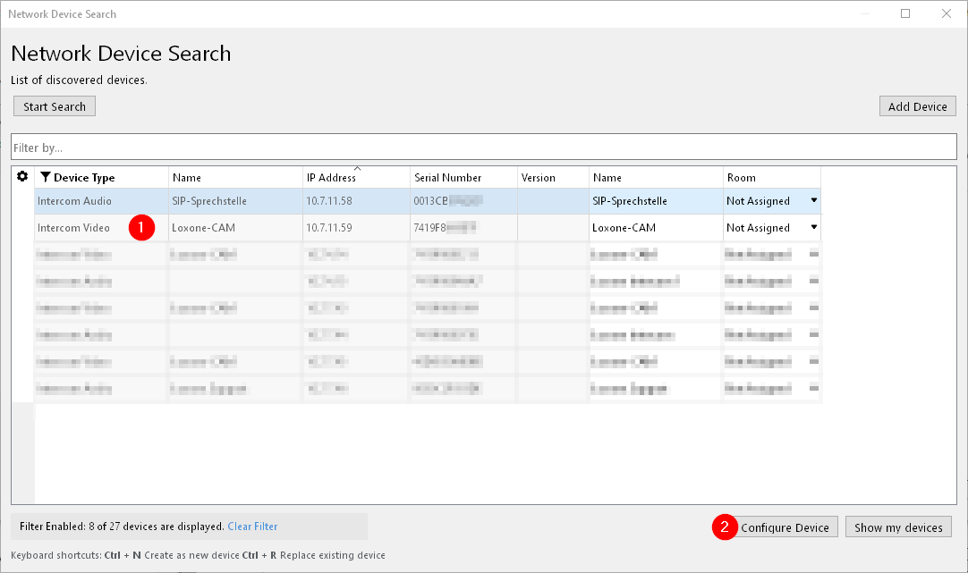
If the Intercom video module was found as described in Step 2, it can now be configured and set up.
- Select the entry for Intercom Video.
- Click the “Configure Device” button.
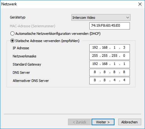
- Assign a static IP address to the module.
- Check and, if necessary, adjust the network settings.
- Then click on “Next”
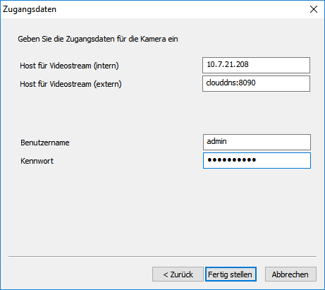
In the following dialog, enter the login details for the video module.
- Enter user name (default user name: “admin”)
- Enter password (default password: “admin”)
- We recommend adjusting the default login credentials after the initial configuration is complete. Information on how to change the password can be found here.
- (Optionally, the external port for the video module can already be configured here. More information about setting up an external video connection can be foundhere)
- Confirm the configuration by clicking the “Finish” button.
Step 4: Create module configuration as network device
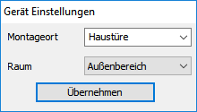
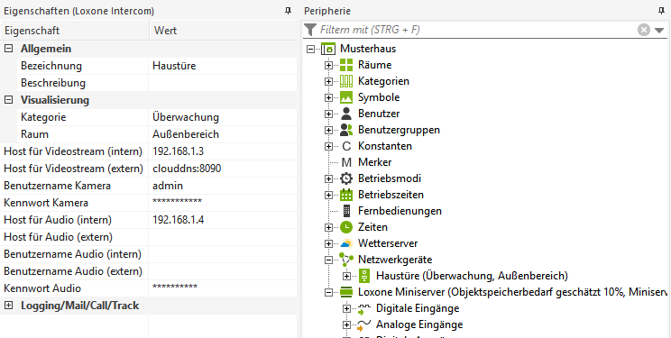
Once the configuration of the Intercom module is completed, it needs to be created as a new network device.
- Enter the installation location.
- Assign to a room.
- Confirm with “Apply”.
In this case, please follow the procedure described in Step 6.
Step 5: Set up Intercom Audio
If the Intercom audio module was found as described in Step 2, it can now be configured and set up.
- Select the entry for Intercom Audio.
- Click the “Configure Device” button.
- It is recommended to assign a static IP address to the module.
- Check and, if necessary, adjust the network settings.
- Then click on “Next”
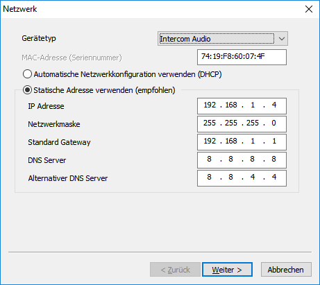
- The selected network settings must match the existing network (network mask, default gateway, etc.).
- The selected IP address must not be in use yet.
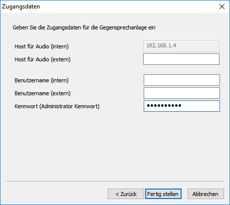
In the following dialog, enter the login details for the audio module.
- Username (internal) is not required.
- Enter password (default password: “admin”)
- We recommend adjusting the default login credentials after the initial configuration is complete. Information on how to change the password can be found here.
- (Optionally, the credentials for the external audio connection can already be entered here. More information about setting up an external audio connection can be found here genauere Infos.)
- Confirm the configuration by clicking the “Finish” button.
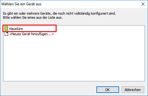
Step 6: Add module configuration to existing network device
Once the configuration of an Intercom module is completed, that configuration can also be applied to another network device.
- Select the desired Intercom.
- Confirm with “OK”
If this is the case, the further procedure is described in step 4.
Step 7: Change login credentials
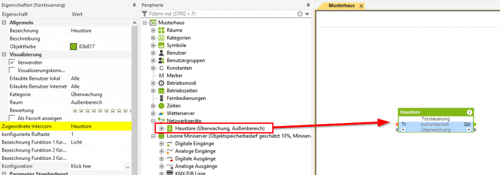
Optional – Adding the Door Controller
- The Door Controller is automatically added by dragging the Intercom onto the desired programmig page.
- The assigned Intercom is automatically selected.
- Save to the Miniserver.
Content
Intercom Video
Inhalt
- Web Interface
- Network Settings
- Network Settings via Loxone Config
- Change password and user
- Set up external video
- Update
- Restore Factory Settings
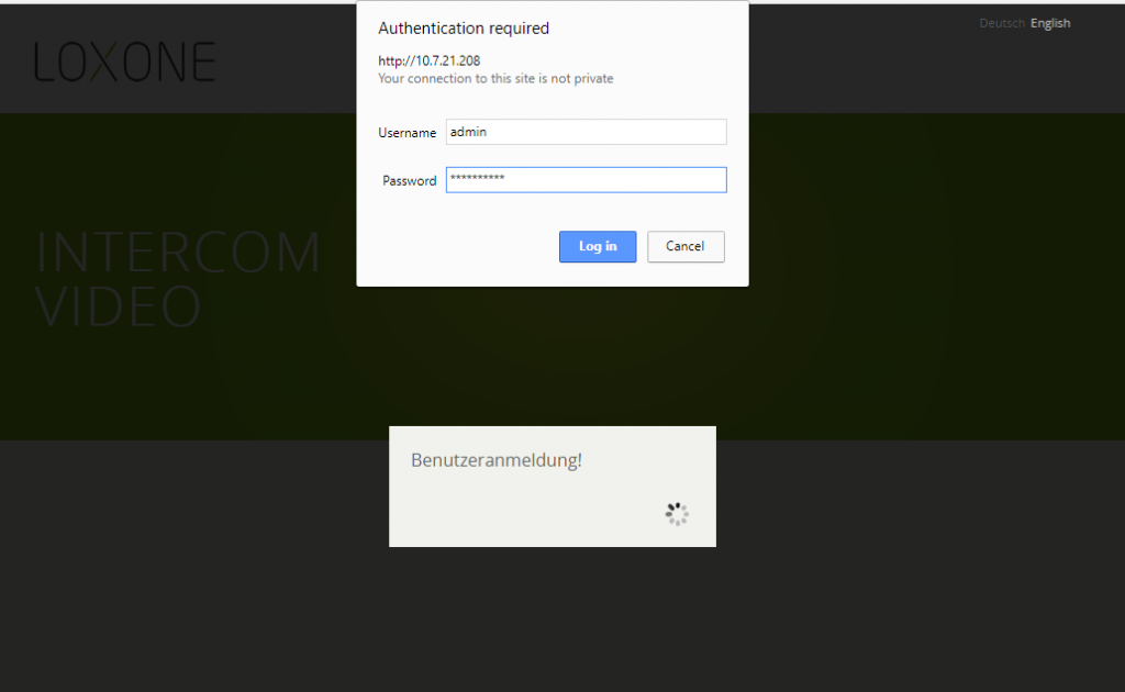
Web Interface
- For this, enter the IP address of the module into your browser.
- Then enter the username and password of the module (default username: admin, default password: admin).
- The start page of the audio module shows the network settings.
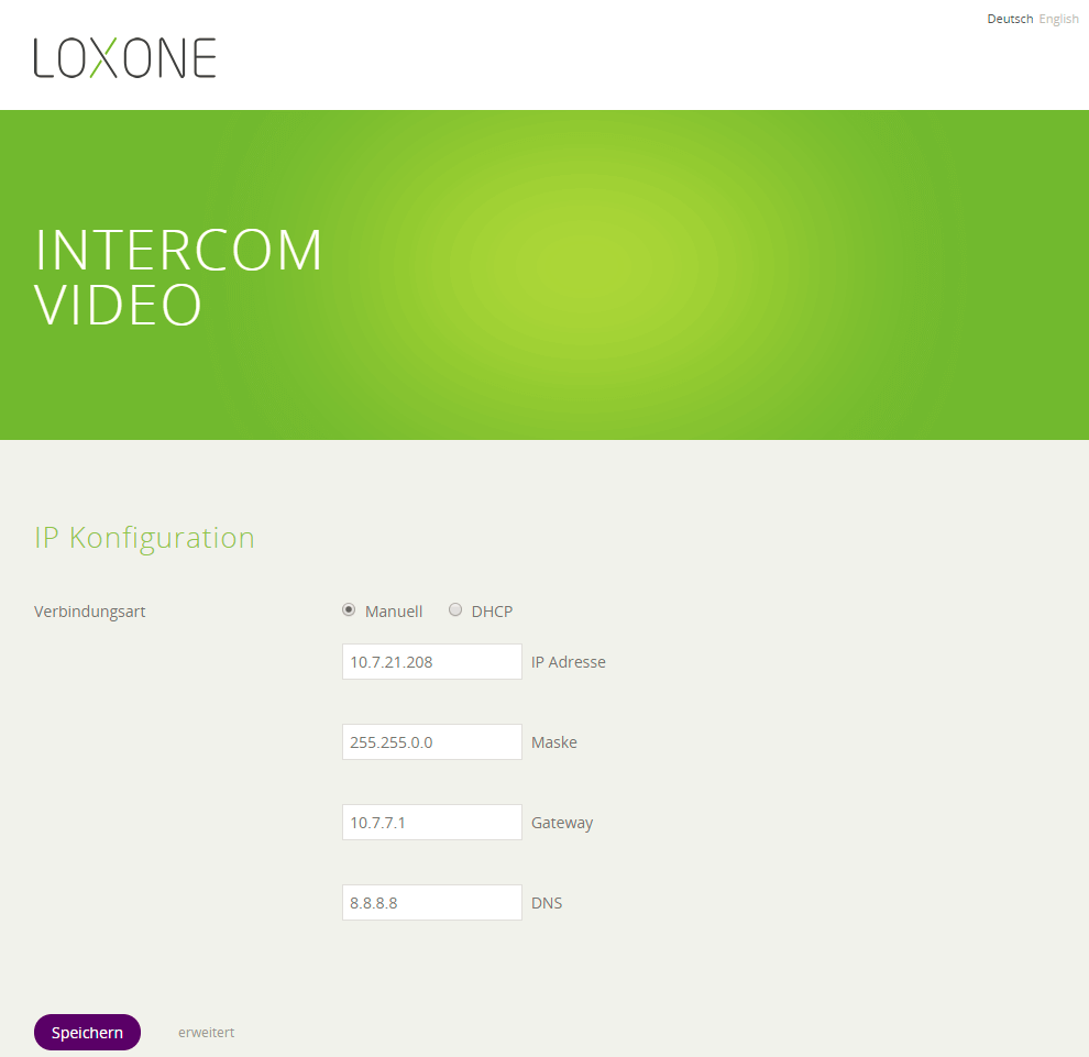
Network Settings
The network settings can also be sent via Loxone Config to the module (detailed information can be found here).
- We recommend assigning a static IP address.
- Please note that the network settings must match your home network (subnet mask, default gateway, etc.).
- The IP address must not yet be assigned.
- Click on “Send” to apply the settings.
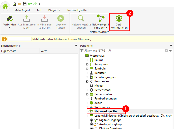
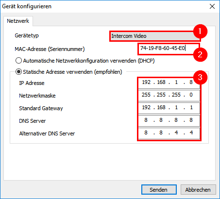
Network Settings via Loxone Config
- Open Loxone Config
- Select “Network Periphery”.
- Select “Configure Device” from the menu.
- Select Intercom Video
- Enter the MAC address of the video module. You can find it on the back of the Intercom.
- Enter the network settings.
- We recommend assigning a static IP address.
- Please note that the network settings must match your home network (subnet mask, default gateway, etc.).
- The IP address must not yet be assigned.
- Click on “Send” to apply the settings.
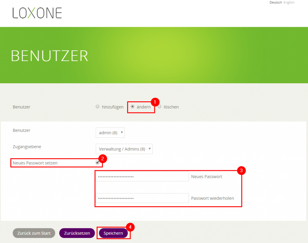
Change Password

Here you can change the current password or create new users.
- Select “Change” user.
- Tick the “Set new password” checkbox.
- Enter your new password.
- Click “Save” to accept the new password.
We recommend creating a new Intercom user for video display in the app. This user should only have “Viewer” rights.
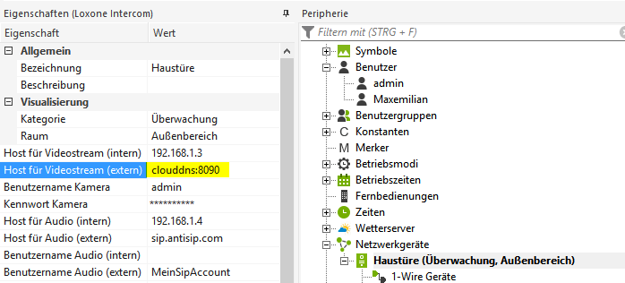
Set up external video
- For external video connection, port forwarding must be set up on the router.
- This is an additional port forwarding similar to the one used for the Miniserver. (More information can be found here)
- For security reasons, always use a random port greater than 5000. 8090 is used in the example.
- Enter the external port in Loxone Config.
- If the Host for Video Stream External is specified with “clouddns:[Port]”, the keyword “clouddns” represents the current external IP address of the connection.
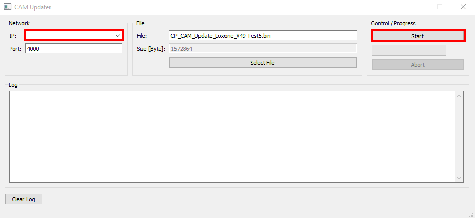
Update
- The default port 4000 does not need to be changed.
- By default, the update file from the extracted folder is used. If necessary, this can be changed via Select File.
Restore Factory Settings
- Power off Loxone Intercom
- Set both DIP switches on the camera module to OFF (normal state: DIP1 = ON, DIP2 = OFF).
- Restore the power supply to the intercom.
- The IP address of the video module is now set to 10.10.10.10.
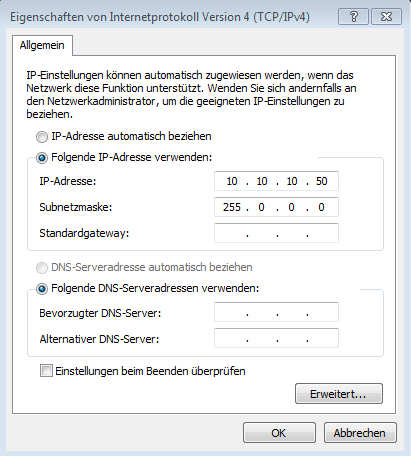
- Now adjust the IPv4 settings of your PC.
- IP Address: 10.10.10.50
- Subnet Mask: 255.0.0.0
- Default Gateway: nicht angegeben
Intercom Audio
Inhalt
- Web Interface
- Network Settings
- Network Settings via Loxone Config
- Change password
- Set up external audio
- Update
- Restore Factory Settings
Web Interface
- For this, enter the IP address of the module into your browser.
- Then enter the username and password of the module (default username: admin, default password: admin).
- The start page of the audio module shows the network settings.
Network Settings
To change the network settings, access the web interface of the audio module (detailed information can be found here).
The network settings can also be sent via Loxone Config to the module (detailed information can be found here).
- We recommend assigning a static IP address.
- Please note that the network settings must match your home network (subnet mask, default gateway, etc.).
- The IP address must not yet be assigned.
- Click on “Save” to apply the settings.
The module restarts automatically after saving.
Network settings with new audio module from 10/2020:
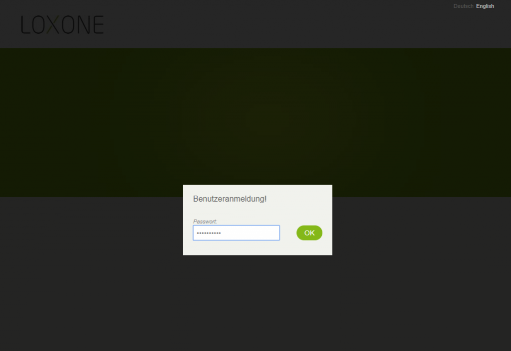
Connect to the web interface of the audio module via browser (configured IP, or default IP 192.168.1.98, default login: admin/admin)
Passwords up to 10 characters in length are supported.
First click on Main (1), then on Main Settings (2).
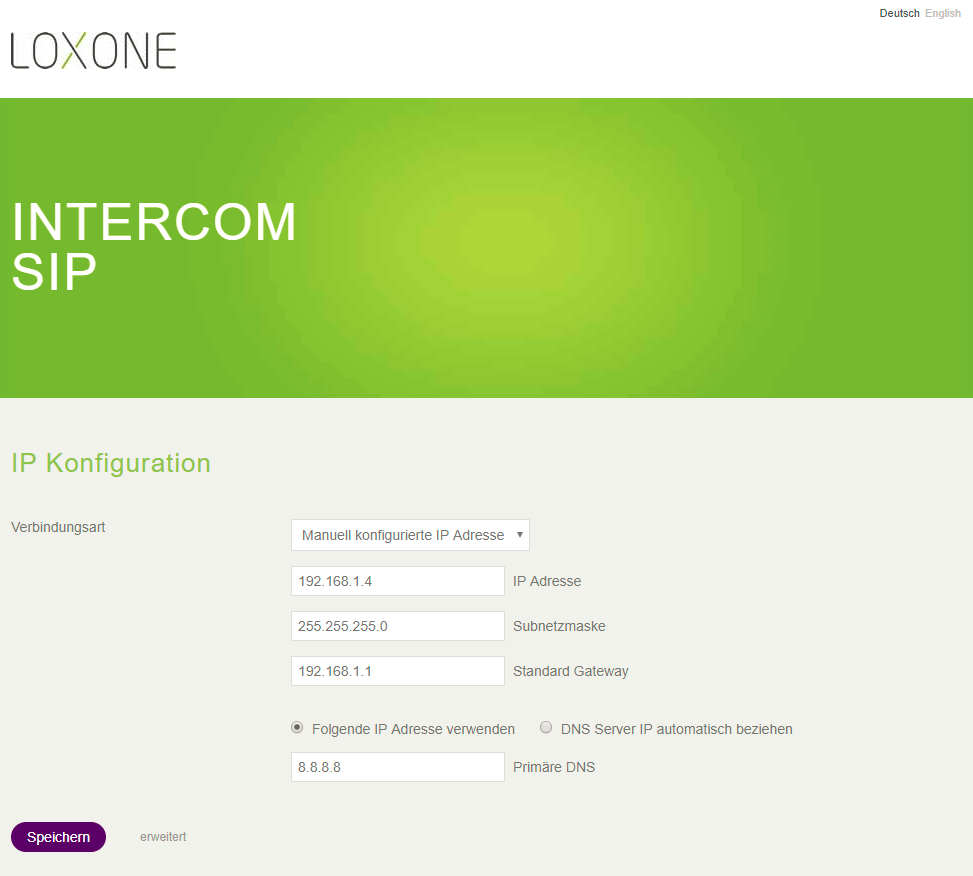
Then configure the IP address (3) and the network settings :
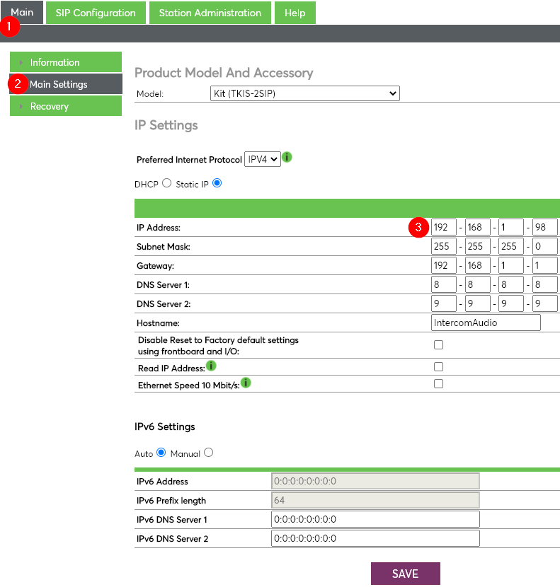
Finally click on “SAVE” to save the settings!
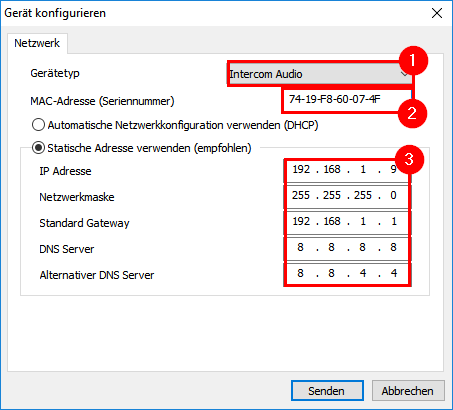
Network Settings via Loxone Config
- Open Loxone Config
- Select “Network Periphery”.
- Select “Configure Device” from the menu.
- Select Intercom Audio
- Enter the MAC address of the audio module. You can find it on the back of the Intercom.
- Enter the network settings.
- We recommend assigning a static IP address.
- Please note that the network settings must match your home network (subnet mask, default gateway, etc.).
- The IP address must not yet be assigned.
- Click on “Send” to apply the settings.
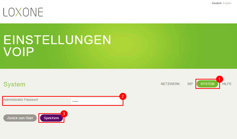
Change Password
- Select “Advanced”.
- Open “VoIP Settings”
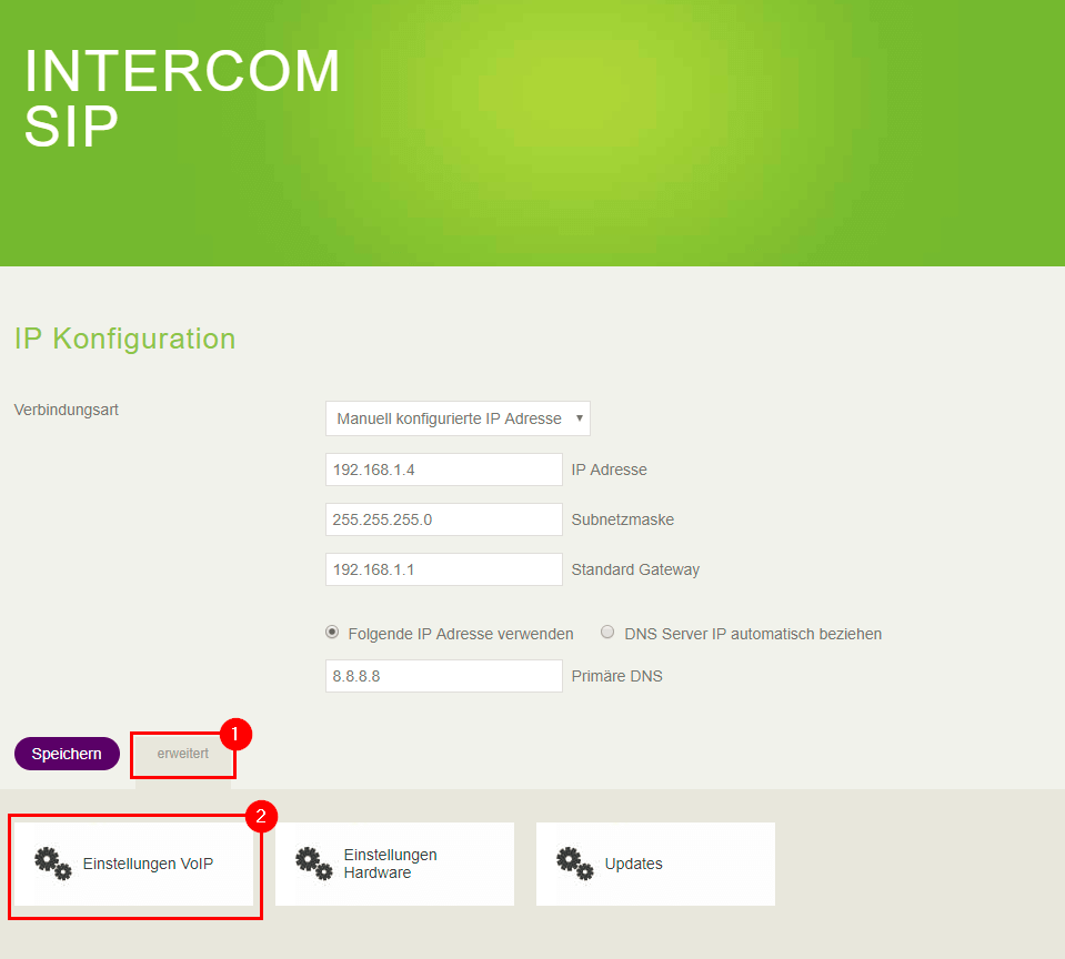
- Select the “System” tab.
- Enter the new password.
- Click “Save” to accept the new password.
Set up external audio
To set up the external audio connection, an external SIP provider like Antisip.com is required.
- A SIP account can be compared to a telephone number, so a separate account is also required for each Intercom.
- An account may not be used more than once!
To link the created SIP account with the Intercom, open the web interface of the audio module (detailed information can be found here).
First, select the “Advanced” button, then open “VoIP Settings”.
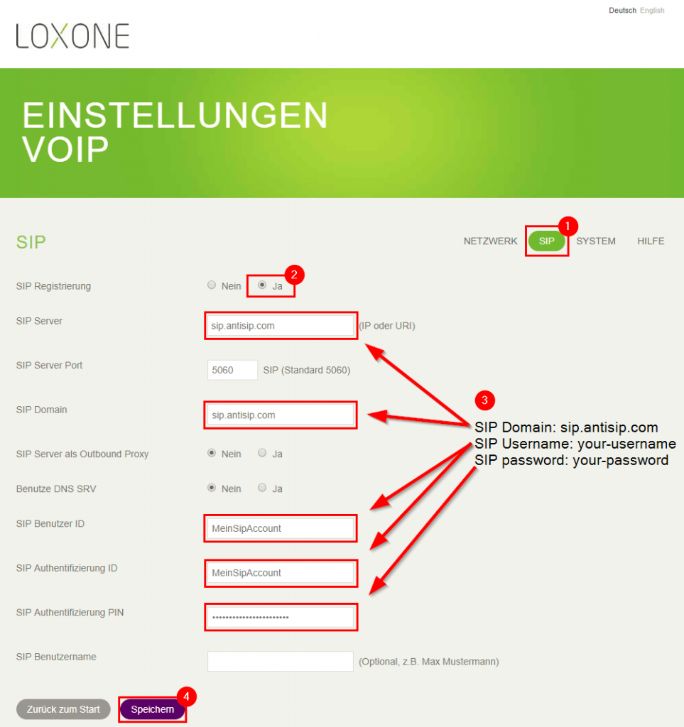
- Select the “SIP” tab
- Set “SIP Registration” to “Yes”.
- Now enter the SIP account data as shown in the image. (This example uses the data of an Antisip account).
SIP settings with new audio module from 10/2020:
Connect to the web interface of the audio module via browser (configured IP, or default IP 192.168.1.98, default login: admin/admin)
Passwords up to 10 characters in length are supported.
First click on SIP Configuration (1)
Then enter the username registered with the SIP account in 2 and 4, and the password at 5.
At 3 enter the SIP server, in the example sip.antisip.com:
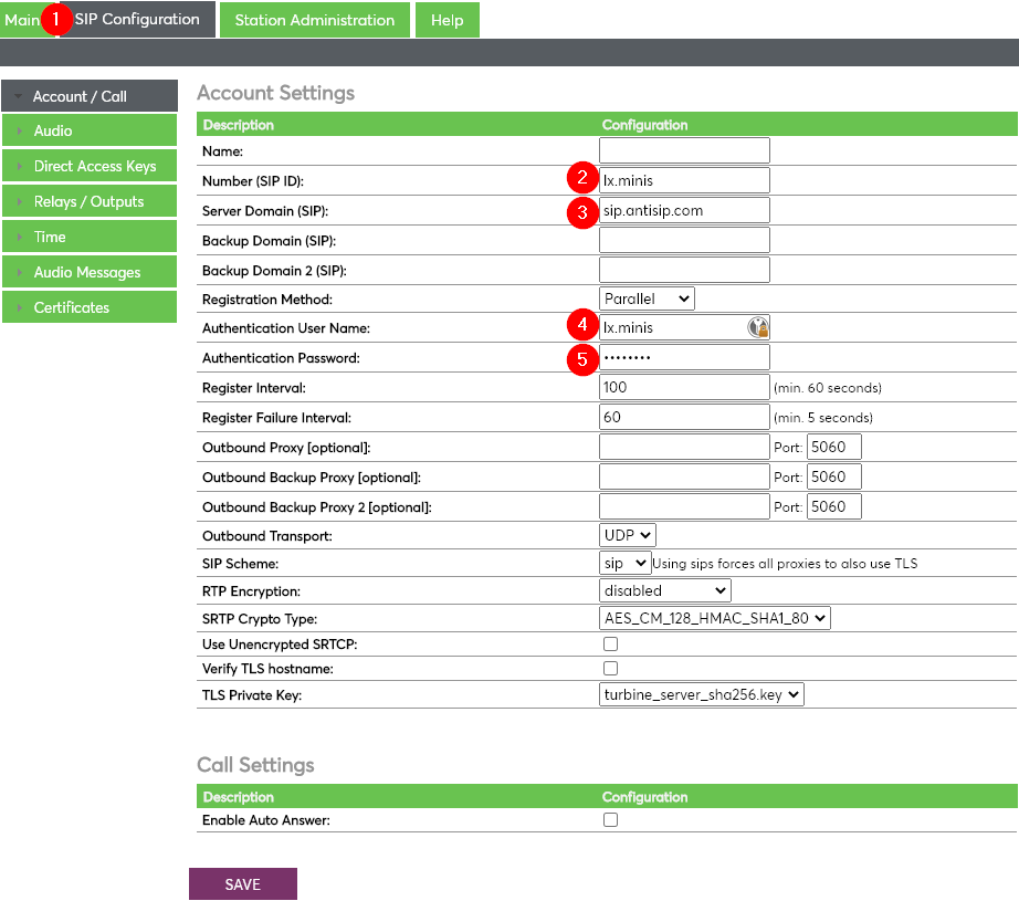
Finally click on “SAVE” to save the settings!
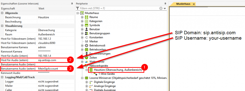
- Select Intercom
- Enter the “Host for audio (external)”.
- Enter the “Audio username (external)”.
Update
 Download firmware for Loxone Intercom / Intercom XL
To update the audio module, access its web interface (detailed information can be found here).
- Download the update file and unzip the compressed folder.
- Select the “Advanced” button.
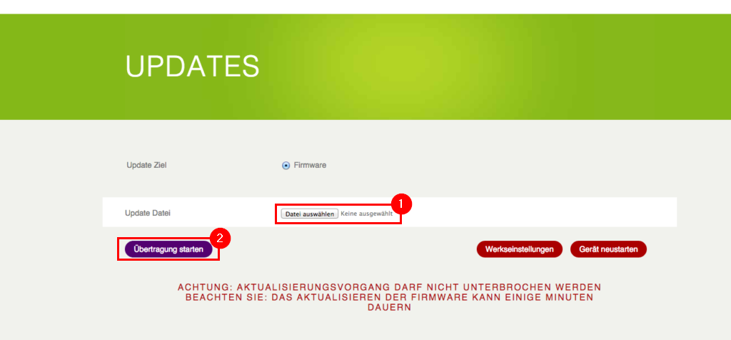
- Select the “Update” setting.
- Select the downloaded update file on your PC (*.bin).
- The update is started by clicking on the “Start transfer” button.
Factory Settings
Intercom Gen. 1 Audio Module before 10/2020
This Version features a reset switch on the circuit board.
- Power off Loxone Intercom
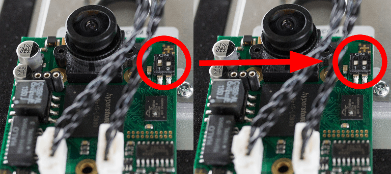
- Set the DIP switch on the side of the audio module to ON (normal state = OFF).
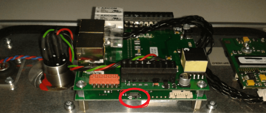
The image shows the normal state (OFF) of the DIP switch. (right position [->]).
-
- Restore the power supply to the Intercom.
- Once the module restarted, you can return the DIP switch to the normal state (OFF).
- The audio module is now accessible at the IP address 192.168.1.98.
- Now connect to the web interface of the audio module (address: 192.168.1.98) Detailed information can be found here.
- Now configure the new network settings for the audio module. Detailed information can be found here.
Intercom Gen. 1 Audio Module after 10/2020
This Version is reset by pressing the doorbell button as follows:
- While pressing the button, power up the station by connecting to a PoE switch
- Hold the button until the station audio starts counting, and release the button on count 1
- Press and hold the button on count 3 and release on count 0
- If there is no 0 count, the procedure has failed and you have to start again
- Press the button, and the station will speak its IP address
Intercom XL
Inhalt
Configure Call Buttons
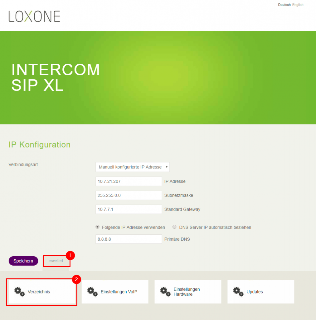
To configure the call buttons, open the web interface of the audio module (Detailed information can be found here).
- Select the “Advanced” button.
- Open the “Directory”.
- Name of the call button (shown as text on the display of the Intercom)
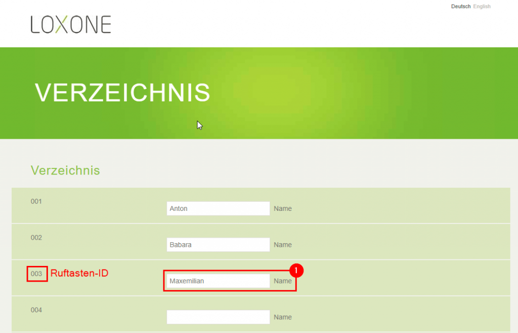
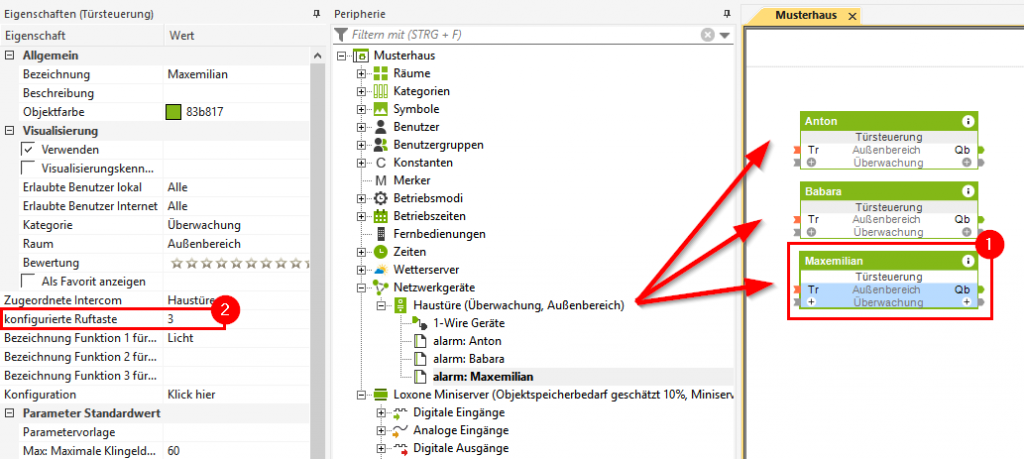
- Select desired Door Controller
- Enter the call button ID
Learn iButton
- Select the Intercom in Loxone Config
- Select the 1-Wire Monitor button
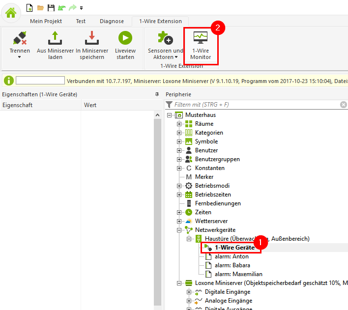
- Hold the iButton to the reader of the Intercom XL.
- Select the iButton
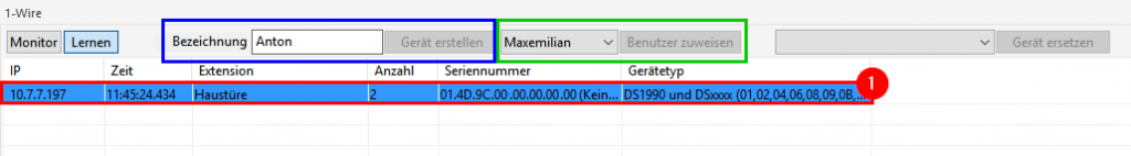
- Create iButton as a device
- Enter a name for the device
- Confirm with “Create device”
- Assign the iButton to a user
- Select the user
- Confirm with “Assign user”
Diagnostics
Inhalt
- Status messages for failed audio connections
- LED States
- No sound during audio connection
- No sound on Android devices
- No image with Internet Explorer
- No image with Google Chrome
- Intercom cannot be found on the network
Status messages for failed audio connections
| “Busy” | Another user is already connected |
| “Please try again later” | The connection is busy, try connecting again at a later time. |
| “The party is (temporarily) unavailable” | Code 480 The system is currently unreachable. Possible causes: |
- SIP account is set up incorrectly. Check the settings in the Intercom and Loxone Config.
- SIP server is not available, check if the system is reachable.
For external connection, check whether the server of the SIP provider can be reached.
“An error was received while establishing the voice connection: <error code>”List of Sip Status Codes“”The other party (__host__) has rejected the call.” Please check the configuration.
“Host or username incorrect”
or.
“Please check the username and host of your audio connection, ‘<userAndHost>’ is invalid.”
Check the account setting in the Intercom and Loxone Config
LED States
Network status
| LED IN | Indicates that a connection to a network is established via X1. |
| LED OUT | Indicates that the connection is forwarded via X2. |
Operating status
| LED2 | LED1 | Description |
| off | off | Idle, connection with SIP server established |
| on | off | Idle, no connection to SIP server established |
| off | on | Establishing a connection to an external party |
| on | on | Loading/saving factory settings |
| on
off |
off
on |
Alternating flashing: Device is in save mode
|
| off | flashing | Factory settings loaded/saved – Jumper can be removed |
| flashing | off | Error loading or saving factory settings or more than one jumper set |
No sound during audio connection
Please check if the SIP module is on the latest firmware version – Click here for update instructions.
- Check the network settings of the SIP module and the Miniserver. A firewall may also be blocking SIP connections – consult a network technician if necessary.
- Check for SIP port overlap with other SIP phones on the same network.
- Check the connection to the SIP service from your network, perhaps the service is not available or the network or the ISP blocks this kind of connection. Consult a network technician if necessary.
- If error messages are returned during an external audio connection, find detailed information here.
No sound on Android devices
No image with Internet Explorer
Starting with Internet Explorer version 6, it is no longer possible to include the user name and password in the URL. However, this is essential for automatic authentication when the camera image is updated by the door station.
This means that not all features of the Door Controller are available with Internet Explorer 6 or higher. We recommend using a different browser, such as Google Chrome or Firefox.
Click here for the Microsoft article discussing this topic
No image with Google Chrome
Google Chrome has changed its authentication method in recent versions, so there may be problems when transmitting images.
Solution:
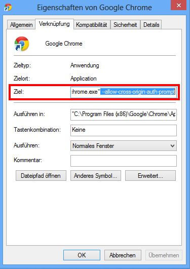
Add the following command to the target path in the Google Chrome icon properties:
“ –allow-cross-origin-auth-prompt“
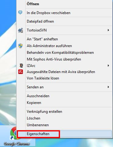
To do this, right-click on the Google Chrome icon and open the properties.
Now, in the “Shortcut” tab, add ” -allow-cross-origin-auth-prompt” to the Target.
The target field should now contain: (may vary depending on operating system and path)
„C:\Program Files (x86)\Google\Chrome\Application\chrome.exe“ –allow-cross-origin-auth-prompt
Intercom cannot be found on the network
If the intercom cannot be found on the local network, follow the steps below.
- Check the connection of the Intercom to your home network (Step 1)
- Check the network settings of the Miniserver and whether they match your existing home network (subnet mask, default gateway, etc.). The IP address must not be assigned twice.
- Send new network settings to the Intercom module via Loxone Config.
- Intercom Video: Detailed information can be found here
- Intercom Audio: Detailed information can be found here
If the settings cannot be sent to the module via Loxone Config:
- Many routers offer an overview of the currently connected devices in your home network. Can you find the Intercom in this overview?
- Intercom Video: Detailed information can be found here
- Intercom Audio: Detailed information can be found here
- If no IP can be obtained via DHCP when starting the Intercom, the IP of the audio module is set to 192.168.1.98 and the IP of the video module is set to 192.168.1.99. Check if these addresses can be reached using a browser.
- Intercom Video: Detailed information can be found here
- Intercom Audio: Detailed information can be found here
If the default addresses are not reachable:
- Connect the network cable of the Intercom directly to your computer.
- Set your computer to a static IP (e.g. 192.168.1.50, subnet mask 255.255.255.0, default gateway remains blank).
- Now try accessing the two default IP addresses again.
- Intercom Video: Detailed information can be found here
- Intercom Audio: Detailed information can be found here
- If both IP addresses are still not available, please reset the modules to factory settings.
Technical Data
Dimensions Loxone XL Intercom
Dimensions Loxone Intercom
The front plate of both the Loxone Intercom and Intercom XL is made of anodized aluminum.
Download
Download
Download