The Dimmer Extension features 4 Output channels for dimming suitable mains voltage luminaires.
Each channel can be set to trailing edge or leading edge dimming, the Dimmer Extension is thus suitable for resistive (incandescent), capacitive (ELV) and inductive (MLV) loads.
Additionally, 8 digital inputs for 24V are available.
Datasheet Dimmer Extension 230V
Datasheet Dimmer Extension 120V
Table of Contents
- Commissioning
- Setting the dimming mode, for 230V
- Setting the dimming mode, for 120V
- Notes on luminaires
- Speed control of motors
- Wave Packet Control
- Inputs, Outputs, Properties
- Safety Instructions
- Documents
Commissioning↑
The Dimmer Extension is installed on a DIN rail in a suitable enclosure.
Connect the power supply and Link communication to the Miniserver and connect the loads on the outputs.
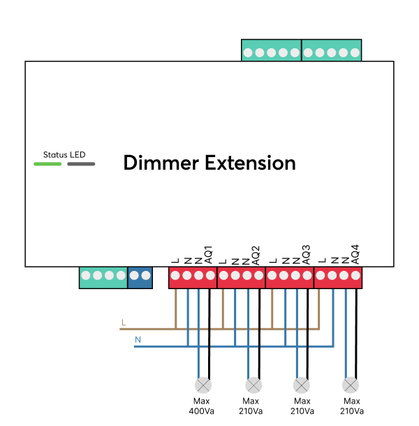
Example 1: 1-phase connection
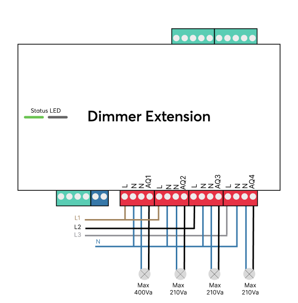
Example 2: 3-phase connection
Example 3: 2 circuits connection

In case of large loads or multiple dimmers, it is advisable to spread the load across several phases as shown in the wiring example. However, a single-phase supply is also possible.
 | Ensure sufficient air circulation to allow the generated waste heat to dissipate, especially at high workloads. |
The Extension starts after switching on the power supply, and the status LED will flash orange after a short time when the connection to the Miniserver is established.
Then follow the pairing procedure on the Link Interface.
Setting the dimming mode, for 230V↑
| Please observe the recommended dimming type and load limits! |
| Only use luminaires that marked as dimmable! |
| Load type | Dimming type | Max. load AQ1 | Max. load AQ2/3/4 | Minimum load |
|---|---|---|---|---|
| Incandescent bulbs | Trailing edge | 400W | 210W | - |
| Mains voltage Halogen lamps | Trailing edge | 400W | 210W | - |
| Low voltage halogen lamps with electronic transformer (ELV) | Trailing edge | 200VA* | 105VA* | - |
| LED light bulb with driver | Trailing edge | 200VA* | 105VA* | - |
| Fluorescent lamp with electronic ballast | Trailing edge | 200VA* | 105VA* | - |
| Mains voltage LED fittings (retrofit, LED bulbs) | Trailing edge or leading edge (rare) | 200VA | 105VA | 50VA for leading edge/inductive |
| Low voltage lamps with magnetic transformer (MLV) | Leading edge | 400VA** | 200VA** | 50VA |
 | *The sum of the nominal load of the ballasts, LED drivers or transformers is relevant, not the nominal load of the actual light. |
| **A magnetic transformer must be loaded with at least 80% of it's capacity! |
| The ballasts, LED drivers, electronic transformers etc. used must be mains voltage dimmable! |
 | If in doubt, the manufacturer of the luminaire can provide information on the load characteristics (whether inductive or capacitive) and the recommended dimming method. |
Setting the dimming mode, for 120V↑
| Please observe the recommended dimming type and load limits! |
| Only use luminaires that marked as dimmable! |
| Load type | Dimming type | Max. load per output | Minimum load |
|---|---|---|---|
| Incandescent bulbs | Trailing edge | 200W | - |
| Mains voltage Halogen fittings | Trailing edge | 200W | - |
| Low voltage halogen lamps with electronic transformer (ELV) | Trailing edge | 100VA* | - |
| LED light bulb with driver | Trailing edge | 100VA* | - |
| Fluorescent lamp with electronic ballast | Trailing edge | 100VA* | - |
| Mains voltage LED fittings (retrofit, LED bulbs) | Trailing edge or leading edge (rare) | 100VA | 50VA for leading edge/inductive |
| Low voltage lamps with magnetic transformer (MLV) | Leading edge | 200VA** | 50VA |
| *The sum of the nominal load of the ballasts, LED drivers or transformers is relevant, not the nominal load of the actual light. |
| **A magnetic transformer must be loaded with at least 80% of it's capacity! |
| The ballasts, LED drivers, electronic transformers etc. used must be mains voltage dimmable! |
| If in doubt, the manufacturer of the luminaire can provide information on the load characteristics (whether inductive or capacitive) and the recommended dimming method. |
Notes on luminaires↑
Incandescent bulbs
Of all luminaires, incandescent lamps are the easiest to dim, this category can also include Halogen lamps and these are an alternative when the highest quality of light is desired and the energy consumption is acceptable.
Generally, incandescent lamps are always dimmable, even if they are not labeled as dimmable. However, for low-voltage halogen lamps, the transformer must be dimmable.
LED illuminant
In principle, all mains voltage LED luminaires marked as dimmable can be dimmed with the Dimmer Extension.
However, characteristics such as the dimming curve, dimming range, and flicker-free dimming can differ for every luminaire. There may also be batch-related differences in LED lamps.
It is advisable to use high-quality luminaires, which guarantee consistent quality and long-term availability.
If possible, test different LED luminaires for dimming quality before purchasing a large quantity.
LEDs flashing or glowing when off
The outputs of the Dimmer Extension are equipped with capacitors for interference suppression. This results in a voltage being measurable at the outputs even when the outputs are switched off, especially without a load. The voltage disappears with even a low load, as there is virtually no power available here.
However, some low-power LED lamps are so sensitive that this can cause occasional flashing or slight glowing. In such a case, use other lamps or a higher number per channel, or switch them off via an additional relay contact.
Speed control of motors↑
The Dimmer Extension can also be used for speed control of motors via leading edge dimming.
However, only certain motors are suitable for this.
Only use this if you have experience with speed control of motors by phase cutting and if it is known that the motor type used can be controlled by leading edge phase cut and that no dangerous voltage peaks occur.
If the motor is not suitable, this can damage both the motor and the Dimmer Extension!
Such damage is not covered by warranty.
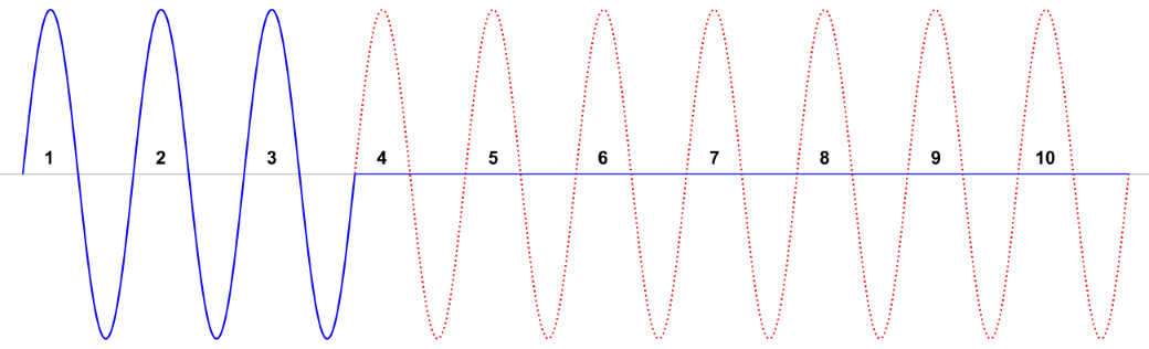
Wave Packet Control↑
We use the "(Classic) control with fixed period duration" mode. The period duration (Modulation Wave Count) can be selected.
This mode is only available when using standard actuators and cannot be selected for older generations of the Extension.
This setting defines the number of full AC wave periods for wave packet modulation. Increasing the number of wave periods results in smoother and more precise control. Fewer wave periods should be used for devices that react quickly, where noticeable on/off modulation behavior would be undesirable.
For example, with a 50Hz line frequency, setting the value to 50 results in a modulation period of 1.0 second. A dim level of 30% would then result in a periodic modulation of 0.3 seconds on and 0.7 seconds off.
Sensors↑
| Summary | Unit | Value Range |
|---|---|---|
| Input 1 | Digital | 0/1 |
| Input 2 | Digital | 0/1 |
| Input 3 | Digital | 0/1 |
| Input 4 | Digital | 0/1 |
| Input 5 | Digital | 0/1 |
| Input 6 | Digital | 0/1 |
| Input 7 | Digital | 0/1 |
| Input 8 | Digital | 0/1 |
Actuators↑
| Summary | Value Range |
|---|---|
| Smart Actuator | ∞ |
| Smart Actuator | ∞ |
| Smart Actuator | ∞ |
| Smart Actuator | ∞ |
Diagnostic Inputs↑
| Summary | Description | Unit | Value Range |
|---|---|---|---|
| Online Status Dimmer Extension | Indicates whether the device can be reached by the Miniserver. Diagnostics for Air devices Diagnostics for Tree devices Diagnostics for Extensions | Digital | 0/1 |
| System temperature | Provides the internal device temperature. This is often the temperature of the CPU or another location in the device. | ° | ∞ |
| Temperature Shutdown | Input is active, when the outputs of the device have been switched off due to high device temperature. Possible reasons: Ambient temperature too high, outputs overloaded. | Digital | 0/1 |
Properties↑
| Summary | Description | Default Value |
|---|---|---|
| Serial Number | Specifies the serial number of the device. Enter 'Auto' to automatically pair an Extension with unknown serial number. This can only be used if there is only one Extension of the same type on a standalone Miniserver (not in a Client-Gateway setup). Save in the Miniserver to pair the Extension. Afterwards the program must be loaded from the Miniserver to transfer the actual serial number of the Extension into the program. | - |
| Monitor Online Status | If checked, you will be notified via System Status or the Mailer if the device is no longer available or goes offline. | - |
| Actuator Type | Use device with Standard Actuator(s) or Smart Actuator(s) Smart Actuators support dynamic fade times and can only be used with the Lighting Controller. | - |
Safety Instructions↑
Installation must be carried out by a qualified electrician in accordance with the applicable regulations.
This device must be mounted on a DIN rail in an electrical distribution enclosure to ensure protection against contact, water and dust.
Only mount the device on a horizontal DIN rail to ensure heat dissipation by convection.
Documents↑
Datasheet Dimmer Extension 230V
Datasheet Dimmer Extension 120V