The Internorm Extension is designed to integrate I-tec devices made by Internorm, e.g. ventilation, shading, window contacts or handheld transmitters.
 | Currently, only Internorm devices with the I-tec 1.0 radio protocol are compatible. The new protocol I-tec 2.0 is not supported! In order to integrate new Internorm I-tec 2.0 devices, they must first be reset to I-tec 1.0. To do this, follow the instructions from internorm. If you need help with this, please contact Internorm customer service. After the change to I-tec 1.0, the devices can be paired with the Internorm Extension. |
Table of Contents
- Commissioning
- Pairing I-tec devices
- Commissioning I-tec devices
- Inputs, Outputs, Properties
- Safety Instructions
- Documents
Commissioning↑
The Internorm Extension is installed on a DIN rail in a suitable enclosure.
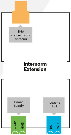
Connect the power supply, Link communication to the Miniserver and install the SMA antenna.
| To ensure optimal signal quality, use the optionally available rod antenna. If the enclosure is made of metal, install the antenna outside the enclosure using the SMA extension cable that is supplied with the rod antenna. Alternatively, a flat self-adhesive SMA antenna is available. |
The Extension starts after switching on the power supply, and the status LED will flash orange after a short time when the connection to the Miniserver is established.
Then follow the pairing procedure on the Link Interface.
Pairing I-tec devices↑
Pairing Mode:
All I-tec devices have to be paired in Loxone Config via the pairing mode. In delivery state, pairing mode will be active after the power supply has been established.
If an I-tec device was previously paired, it must be put back into pairing mode. More information can be found in the device's operating instructions.
Searching and pairing:
To search for I-tec devices, first click on the Internorm Extension in Loxone Config, and then activate Internorm Device Search
The window that opens will list all I-tec devices that are in pairing mode:
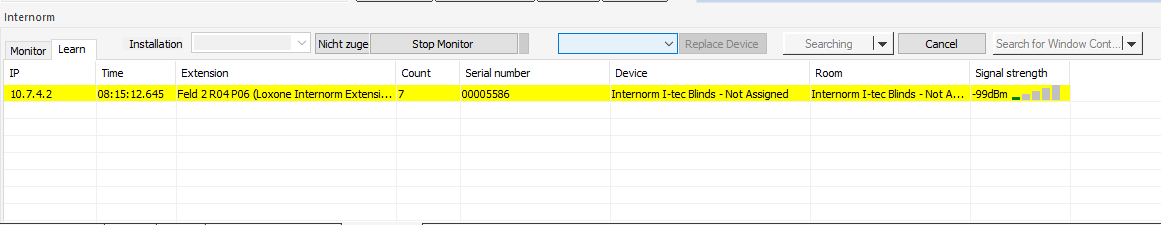
Select a device, assign a room and installation location and click on Create Device.
To apply the changes, save the program in the Miniserver.
Now the added devices are ready for use and the functions are available in the Periphery Tree in Loxone Config.
Pairing window contacts:
Since the I-tec window contact uses a different communication protocol, the pairing process is slightly different.
Start the Internorm Device Search as described above. In the search window, click on the button Search for Window Contact
Once the search is running, insert the batteries into the window contact. If they are already inserted, remove the batteries briefly and then reinsert them.
Within a few seconds the window contact is displayed.
Select a device, assign a room and installation location and click on Create Device.
To apply the changes, save the program in the Miniserver.
| I-tec window contacts on firmware version B11211 or higher are supported. For window contacts dated before March 2018, a firmware update by Internorm Customer Service is required. |
Notes:
 | Please note that I-tec devices cannot be paired with each other and the Internorm Extension. For example, an I-tec handheld transmitter may only be paired with either an I-tec shading device, or the Internorm Extension. |
I-tec devices of the same device type cannot be identified during the pairing process. Therefore, either pair the devices one by one, or do not assign to room and installation location until after pairing, e.g. by testing the shading device.
Commissioning I-tec devices↑
For additional information on the various I-tec devices please visit the documentation on our website:
Commissioning Internorm I-tec Devices
Diagnostic Inputs↑
| Summary | Description | Unit | Value Range |
|---|---|---|---|
| Online Status Internorm Extension | Indicates whether the device can be reached by the Miniserver. Diagnostics for Air devices Diagnostics for Tree devices Diagnostics for Extensions | Digital | 0/1 |
Properties↑
| Summary | Description | Unit | Value Range | Default Value |
|---|---|---|---|---|
| Serial number | Specifies the serial number of the device. Enter 'Auto' to automatically pair an Extension with unknown serial number. This can only be used if there is only one Extension of the same type on a standalone Miniserver (not in a Client-Gateway setup). Save in the Miniserver to pair the Extension. Afterwards the program must be loaded from the Miniserver to transfer the actual serial number of the Extension into the program. | - | - | - |
| Polling and transmission cycle | Polling an transmission cycle: Device sensors are queried in this cycle. For devices that have offline monitoring, this cycle is also used for offline detection. If the signal strength is poor, it is recommended to increase the transmission cycle. | min | 30...240 | 30 |
| Coordinated command transmission | The Extension coordinates the transmission of RF commands with other Internorm Extensions in order to avoid possible radio interference between them. This increases the reliability, but can lead to slight delays. | - | - | - |
| Monitor online status | If checked, you will be notified via System Status or the Mailer if the device is no longer available or goes offline. | - | - | - |
Safety Instructions↑
Installation must be carried out by a qualified electrician in accordance with the applicable regulations.
This device must be mounted on a DIN rail in an electrical distribution enclosure to ensure protection against contact, water and dust.