The new protocol I-tec 2.0 is not supported!
GENERAL INFORMATION
Learn more about the supported I-tec I-tec devices with Loxone, currently the following I-tec devices can be used on Internorm Extension:
- I-tec Ventilation
- I-tec Shading
- I-tec Hand transmitter
- I-tec Window Contact
As soon as a device is integrated into the Internorm Extension, all previous assignments of the device are deleted.
I-TEC VENTILATION
In order to be able to control your I-tec ventilation with the Miniserver, the device must be learnt into the Internorm Extension.
Details on how to learn in the I-tec ventilation can be found here.
If the fan has already been taught in, it must first be unlocked.
To unlock the fan, proceed as follows:
Standby mode:
Press the + button and the Auto button for 10 seconds -> All the LEDs flash ->
Button – Press within 15 seconds -> Fan is unlocked.
Instruction manual for i-tec Ventilation
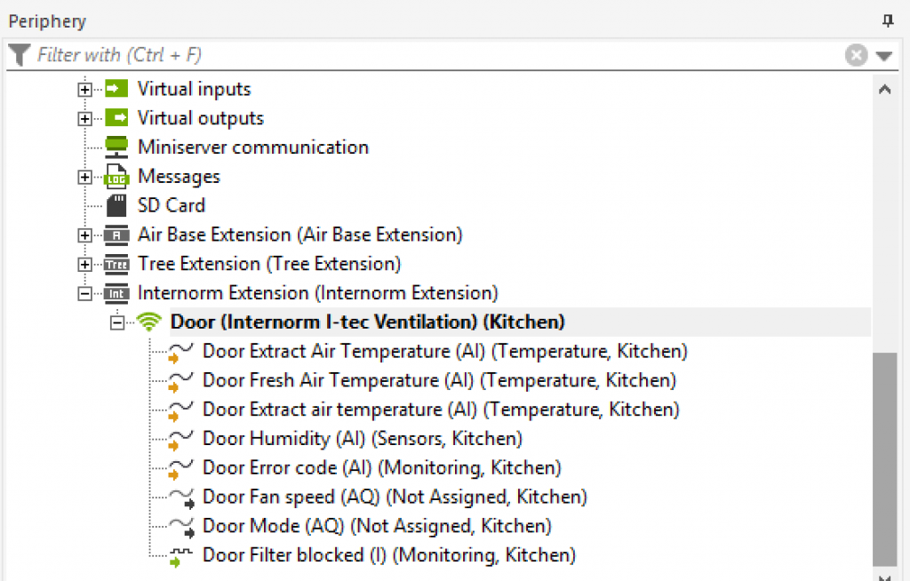
The device will now be listed in the Periphery Tree of Loxone Config.
The following objects are available in the programming:
- Temperature extract air = temperature of the air sucked into the room
- Temperature Fresh air = temperature of the outside air sucked in
- Temperature air = temperature of the extracted air after the heat exchanger
- Humidity = humidity of the air sucked into the room
- Speed of fan = 0-100%
- Mode:
- 0 = supply and extract air
- 1 = supply air
- 2 = extract air
Furthermore, diagnostic inputs can be activated in the properties of the device, this can also display:
- Error codes
- Filter change
If the fan does not react to control but the sensor values are showing, please check the error output. If the code shows ‘100’ then an update of the fan will be required by your Loxone Partner.
| Code: | Issue | Information |
| 100 | Outdated Firmware | Contact your Internorm partner for a firmware update |
| 101 | Error: Exhaust Air Temp Sensor | Temperature values outside limits. Contact your Internorm partner |
| 102 | Error: Fresh Air Temp Sensor | Temperature values outside limits. Contact your Internorm partner |
| 103 | Error: Room Air Temp Sensor | Temperature values outside limits. Contact your Internorm partner |
| 104 | Error: Humidity Sensor | Humidity values outside limits. Contact your Internorm partner |
| 105 | Error: Exhaust Air Fan | Fan motor is stuck. Check whether visible objects are stuck in the ventilation shafts. If the problem cannot be solved, contact your Internorm Partner. |
| 106 | Error: Supply Air Fan | Fan motor is stuck. Check whether visible objects are stuck in the ventilation shafts. If the problem cannot be solved, contact your Internorm Partner. |
| 107 | Error: Supply Voltage | The fan has reported an error with the power supply. Contact your Internorm partner. |
| 108 | Error: EEPROM | Configuration values may not be saved correctly. Contact your Internorm partner. |
| 110 | Error: EEPROM Communication | Configuration values may not be saved correctly. Contact your Internorm partner. |
| 111 | Error: HMI Communication | Control keys cannot be queried. Check that the control panel is correctly mounted on the ventilation unit. If there are no visible problems, contact your Internorm partner. |
| 112 | Error: Temperature Sensor Communication | Temperature Sensor cannot be queried. Check that the control panel is correctly mounted on the ventilation unit. If there are no visible problems, contact your Internorm partner. |
| 114 | Error: Temp Sensor over/under limits | Temperature sensor has reported a value outside its limits. Contact your Internorm Partner. |
| 115 | Error: WRM Communication | Ventilation unit has lost connection to wireless module. Check that the control panel is correctly mounted on the fan. If there are no visible problems, contact your Internorm partner. |
I-TEC SHADING
In order to be able to control your I-tec shading with the Miniserver, the device must be learnt into the Internorm Extension.
Details on how to learn in the I-tec shading can be found here.
In the Loxone Config, I-tec shading is controlled by the Integrated Blinds function block.
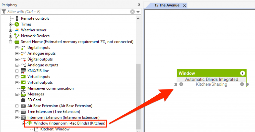
Simply drag the inserted Internorm i-tec shading onto the desired program page.
The curtain type (roller/blind) can be set in the properties of the i-tec device.
In addition, you can define the travel time for a complete journey.
To do this, stop a complete travel of the blind. The set travel time serves for a correct visualisation in the UI and has no influence on the control of the shading.
NB: The I-Tec shading can be learnt in even when it has a very low battery level. If a command to drive the blind in a direction is then sent after learning the blind in, it will only be actioned if the battery has a minimum battery level. As such if the battery level is less than 20% then the blind may not move whena command is sent.
Details of the block can be found here.
I-TEC REMOTE
In order to be able to control your I-tec remote with the Miniserver, the device must be learnt into the Internorm Extension.
Details on how to learn in the I-tec remote can be found here.
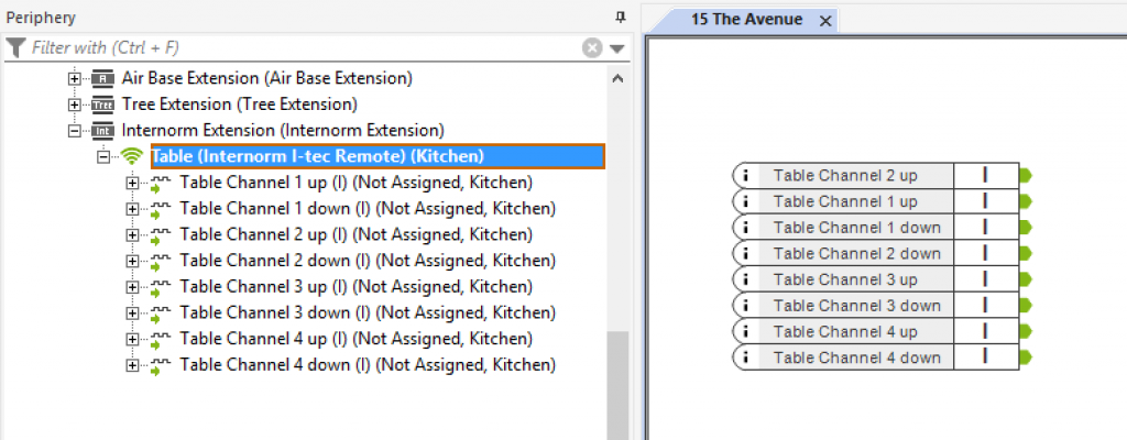
After you have learned the hand-held transmitter, the touch points in the Loxone Config can be used as digital inputs. An up and down input is available for each of the 4 channels.
The channel can be changed via the third button.
I-TEC WINDOW CONTACT
From Loxone Config version 8.3, you can also teach your I-tec window contact to the Miniserver.
Details on how to learn in the I-tec window contact can be found here.
After you have entered the window contact, the following inputs are available:
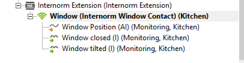
Using the Window Contact
The window contact offer one analogue input “Position”, and two digital inputs “Closed” and “Tilted”
Position
The analogue input “position” works in the same way as the analogue input of the Window Handle AIr.
0: Unknown (Has not yet received any data, can happen just after pairing the device. To fix this, briefly open or close the window.)
1: Closed: Window completely closed and locked
2: Titled
3: Open: Window not locked. Tilting windows are are also detected as open.
Digital Input “Closed”
Indicates that the window is locked. When ON, the window is locked
Digital Input “Tilted”
Indicates whether the window is tilted. If ON, the window is tilted.
Diagnostics Inputs
The diagnostics inputs are hidden inputs and can be displayed in the Window Contact properties by clicking on “Display diagnostics inputs”
Battery Status and Battery Low.
The battery status is updated at the same time as the window status.
If no battery status is displayed, the window has not been moved since pairing.
Online Status
The online status indicates whether regular status updates have been received from the window contact. In normal operation, the contact should report its status every 10 minutes at the latest. If this communication was not received, the contact is displayed as offline.