Este bloque controla las unidades de fancoil típicamente utilizadas en edificios comerciales y hoteles.
Basado en la temperatura actual de la habitación (ϑc) y la temperatura de consigna(ϑt), el volumen de aire se regula a través de un controlador PI.
Las válvulas de calefacción y refrigeración se controlan en función de la demanda.
Contenido
Entradas↑
| Abreviatura | Resumen | Descripción | Unidad | Rango de valores |
|---|---|---|---|---|
| ϑc | Current Room Temperature | El valor será proporcionado por el Controlador de Habitación conectado. Si también se utiliza la entrada, se aplica el cambio más reciente. | ° | ∞ |
| ϑt | Target Room Temperature | El valor será proporcionado por el Controlador de Habitación conectado. Si también se utiliza la entrada, se aplica el cambio más reciente. | ° | ∞ |
| Ha | Heating Available | Confirmación de que la energía de calefacción está disponible en esta unidad. Utilice de forma independiente (por ejemplo, bomba de calor "lista", habilitación de caldera) o junto con un Controlador Central de Fancoil como una verificación local de que el agua caliente ha llegado a la unidad (protección de tiempo de tránsito). VERDADERO / no conectado: la calefacción puede funcionar bajo demanda. FALSO: salida de calefacción forzada a apagarse, evita que se sople aire frío en la habitación. Si se asigna a un Controlador Central: combinado con AND con la información del controlador central. | - | 0/1 |
| Ca | Cooling Available | Confirmación de que la energía de enfriamiento está disponible en esta unidad. Utilice de forma independiente (por ejemplo, enfriador "listo") o junto con un Controlador Central de Fancoil como una verificación local de que el agua fría ha llegado a la unidad (protección de tiempo de tránsito). VERDADERO / no conectado: el enfriamiento puede funcionar bajo demanda. FALSO: salida de enfriamiento forzada a apagarse, evita que se sople aire caliente en la habitación. Si se asigna a un Controlador Central: combinado con la información del controlador central mediante una operación lógica AND. | - | 0/1 |
| Dwc | Door and Window Contact | 0 = Cerrado 1 = Abierto | - | 0/1 |
| Rtd | Reset to default | Restablece los parámetros y la configuración del bloque de función a los valores por defecto guardados en una plantilla. ¡Esta funcionalidad solo es posible cuando se usa una plantilla! | - | 0/1 |
| Off | Off / Lock | Apagado / Bloqueo | - | 0/1 |
| Sm | Silent Mode | Cuando se activa, la velocidad máxima del ventilador se establece de acuerdo con la configuración de "Velocidad del Ventilador en Modo Silencioso". Cuando se desactiva nuevamente, la velocidad del ventilador se recalculará. | - | 0/1 |
| Bm | Boost Mode | Establece la velocidad del ventilador al máximo. | - | 0/1 |
| Pt | Pause Timer | Pone en pausa el dispositivo durante el tiempo establecido en el parámetro (Ptd). | - | 0/1 |
| Fan | Fan Speed | Velocidad del ventilador en porcentaje de la potencia total. -1 para automático. -1 si no está conectado. | % | -1...100 |
Parámetros↑
| Abreviatura | Resumen | Descripción | Unidad | Rango de valores | Valor por defecto |
|---|---|---|---|---|---|
| Fmax | Maximum Fan Speed in Auto Mode | Velocidad máxima del ventilador en modo automático | % | 0...100 | 80 |
| Mode | Mode | 0 = Apagado 1 = Automático 2 = Calefacción 3 = Refrigeración 4 = Ventilación Si se configura en Automático y se controla por IRC, será ajustado por el IRC | - | 0...4 | 1 |
| Ptd | Pause Timer Duration | Comienza con el flanco ascendente de la entrada (Pt). Mantiene el dispositivo en pausa durante la duración especificada. | s | 0...∞ | 7200 |
| FϑKP | Proportional Gain (Fan) | Ganancia proporcional para la salida del ventilador basada en la temperatura. Utilizada para el controlador PI. | - | 0...∞ | 50 |
| FϑKI | Integral Gain (Fan) | Ganancia integral para la salida del ventilador basada en la temperatura. Utilizada para el controlador PI. | - | 0...∞ | 0.01 |
| FϑSt | Sample Time (Fan) | Tiempo de muestreo para la salida del ventilador en función de la temperatura. Utilizado para el controlador PI. | s | 0...∞ | 60 |
Salidas↑
| Abreviatura | Resumen | Descripción | Unidad | Rango de valores |
|---|---|---|---|---|
| H | Heating Output | Salida de calefacción | - | 0...10 |
| C | Cooling Output | Salida de Refrigeración | - | 0...10 |
| HC | Combined Heating/Cooling Output | Salida combinada de calefacción/refrigeración | - | 0...10 |
| Fan | Fan Speed Analogue | Velocidad del ventilador analógica | - | 0...100 |
| FanS | Fan Speed Step | Paso actual calculado con la configuración de "Pasos de Velocidad del Ventilador". | - | 0...∞ |
| ϑc | Current Room Temperature | Temperatura ambiente actual | ° | ∞ |
| ϑt | Target Room Temperature | Temperatura de consigna | ° | ∞ |
| Mode | Current Mode | 0 = Apagado 1 = Automático 2 = Calefacción 3 = Refrigeración 4 = Ventilación | - | 0...4 |
| S | Status | Encendido cuando alguna válvula esté abierta o el ventilador esté activo. | - | 0/1 |
| API | API Connector | Conector basado en API. Puede vincular varias funciones entre dispositivos y bloques. La Zona del Servidor de Música no es compatible con Touch Pure Flex. Comandos API | - | - |
Propiedades↑
| Resumen | Descripción | Unidad | Rango de valores | Valor por defecto |
|---|---|---|---|---|
| Pasos de velocidad del ventilador | Para mapear pasos discretos. Ejemplo: 4 pasos -> 25% de la potencia total para cada paso. Establecerlo en 0 desactiva la salida de Velocidad de Ventilador por Pasos (FanS). | - | 0...100 | 3 |
| Velocidad del ventilador en modo silencioso | Velocidad máxima del ventilador en modo silencioso | % | 0...100 | 10 |
Descripción funcional↑
Este bloque regula el volumen de aire, así como la producción de calor y frío en función de la temperatura actual y la temperatura de consigna.
El volumen de aire solo se incrementa según sea necesario para mantener la temperatura de consigna, ya que volúmenes de aire más altos conducen a mayores pérdidas de energía.
Las salidas se controlan de acuerdo con la siguiente lógica de operación:
| Modo de Operación | Volumen de Aire | Salida de Calefacción | Salida de Refrigeración |
|---|---|---|---|
| Calefacción | ϑ variable | 100 % | 0 % |
| Refrigeración | ϑ variable | 0 % | 100 % |
| Todo OK | 0 % | 0 % | 0 % |
ϑ variable
El volumen de aire se ajusta dependiendo de la diferencia entre la temperatura actual y la temperatura de consigna.
La calefacción o la refrigeración funcionan a plena capacidad.
 | Para garantizar un control estable y no disruptivo, el volumen de aire se ajusta una vez por minuto, con cambios limitados a un máximo del 20%. Como resultado, un ajuste completo del 100% al 0% requiere cinco minutos. |
Ejemplo de programación↑
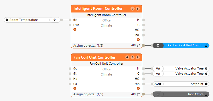
Combinación con Controlador de Habitación
Las válvulas de calefacción y refrigeración, así como el ventilador, están conectados a las salidas correspondientes del bloque.
El Controlador de la Unidad de fancoil se puede conectar al Controlador de Habitación a través del Conector API:
En la ventana de propiedades, se pueden ajustar los parámetros del controlador PI para la regulación del ventilador basada en la temperatura:
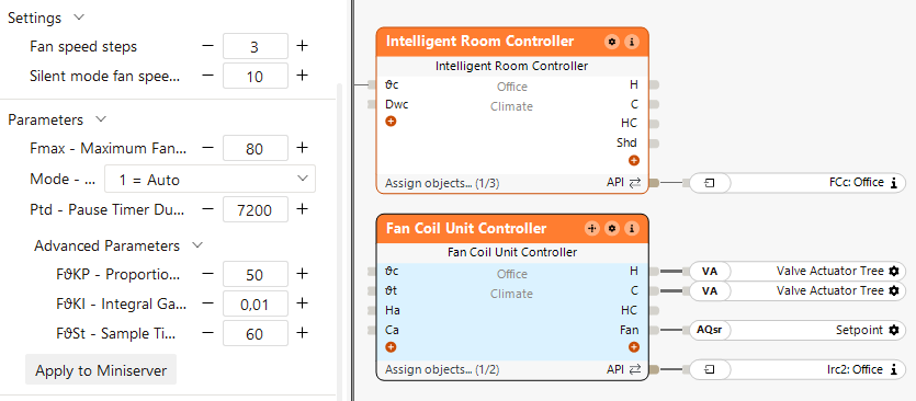
Dado que en este ejemplo se utiliza un sistema de 4 tubos, no es necesario conectar las entradas (Ha) y (Ca), ya que se da por supuesto que la calefacción y la refrigeración están disponibles de forma predeterminada.
El Controlador de Habitación maneja la lógica de la habitación y pasa los valores de temperatura y los requisitos de calefacción/refrigeración al Controlador de la Unidad de fancoil.
Esto ajusta el volumen de aire y las válvulas de calefacción/refrigeración.
Combinación con Controlador de Habitación y Controlador Central de unidad fancoil
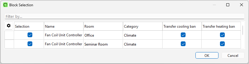
Al hacer doble clic en el bloque central, se pueden agregar los correspondientes Controladores de Unidad de fancoil:
En la ventana de propiedades, el tipo de sistema (2-tubos o 4-tubos) se puede seleccionar directamente:
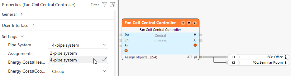
El Controlador Central de fancoil recopila las demandas y decide entre calefacción y refrigeración.
Basado en esta decisión, los Controladores de la Unidad defancoil ajustan las válvulas y el volumen de aire en las habitaciones respectivas.
Este bloque también puede operar de forma independiente. En este caso, los valores de temperatura se pasan directamente al bloque a través de las entradas..