The Loxone Valve Actuator Air is a wireless motorized valve actuator for heating systems. By using common adapter rings, it can be mounted on a wide range of valves, which are typically used for radiant floor heating and radiators.
Datasheet Valve Actuator Air Gen.1
Table of Contents
- Mounting
- Commissioning
- LED states
- Device test and calibration run
- Battery Replacement
- Inputs, Outputs, Properties
- Safety Instructions
- Documents
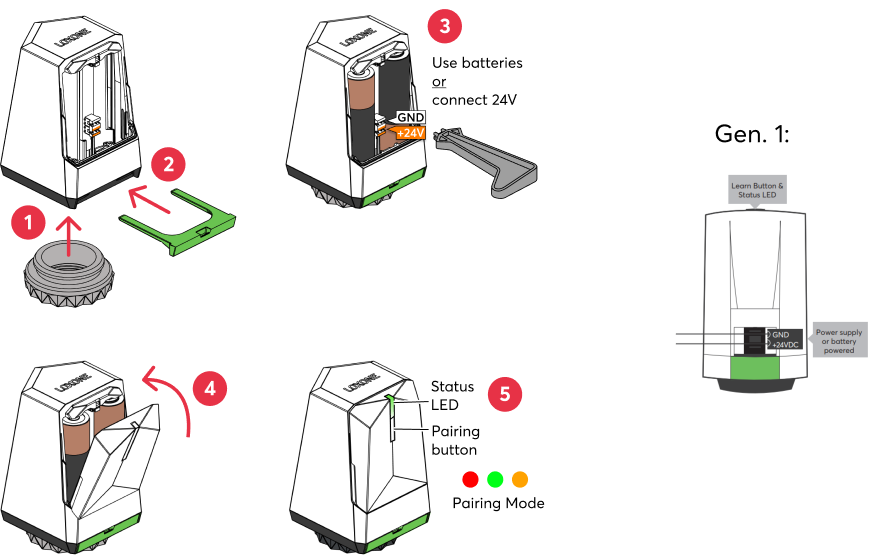
Mounting↑
In delivery state, the valve is fully open. The Valve Actuator Air performs a calibration run after pairing, so it must be installed before initial start-up. Before mounting, make sure that the valve pin is movable and not rusted.
Then snap the actuator onto the adapter ring. Do not apply excessive force. Make sure that the actuator is correctly positioned on the valve. Only use valve adapters suitable for the valve.
 | Ensure that the correct adapter is used for the specific valve type. Using an unsuitable adapter may lead to issues, such as "valve stuck" or "no valve detected" messages. The adapter also positions the valve stem correctly. |
Then use either the supplied batteries or connect an external 24VDC power supply.
If the actuators are to be hardwired, we recommend using the Loxone Tree Cable or Panel Wire, both 0.8mm Ø.
Use the IDC tool to push the orange/white wire pair to connect the power supply.
We recommend a short service loop between the individual actuators and securing the cable near the first actuator for strain relief.
The wires are pressed into the terminals of the actuators using the terminal cover, or the IDC Tool (100226) supplied with the Miniserver or Tree Extension.
| Make sure that no water can drip onto the actuator. Although the actuator can be mounted in any position, it is recommended to install the actuator above the valve to prevent water dripping onto the actuator in case of a leaking valve or condensation. |
| When installing the Valve Actuator, ensure that the opening for the green mounting clip does not face downward. Installing the Valve Actuator in this position may cause the clip to loosen or fall out, potentially leading to malfunction or improper operation of the valve. |
 | If a large number of valve actuators share one electrical line with a small wire cross-section, significant voltage drop may occur. In such a case, it is recommended to use a larger wire cross-section for the 24V supply line and to switch to a smaller cross-section just before connecting the actuators. |
Commissioning↑
In delivery state, pairing mode will be active after the power supply has been established. This is indicated by the status LED flashing red/green/orange.
Then follow the pairing procedure on the Air Interface.
To activate the pairing mode manually, hold down the pairing button for at least 5 seconds immediately after inserting the battery.
After pairing, the calibration run starts. The Valve Actuator determines the valve travel and registers the 0% and 100% positions.
By default, the actuator then moves to the 0% position (valve closed). Programming must be created to open the valve again.
The available functions differ depending on whether the device is battery operated or connected to an external power supply. This is determined during pairing. The device must therefore be paired in the same supply method in which it is to be operated later.
If the supply method is changed later, the device must be deleted from the programming and paired again.
LED states↑
| LED state | Description |
|---|---|
| Device is in pairing mode, ready for pairing. |
| 3 short flashes Device was successfully paired. |
| Air device is offline. |
| Device was selected in Loxone Config and is identifying (if powered with 24V). |


Device test and calibration run↑
The actuator can be fully opened or closed for test purposes.
In addition, the actuator can be recalibrated.
If the actuator is battery powered , it must first be woken up.
Then right-click on the actuator in the Periphery tree and select an option:
Device test on: Fully open actuator/valve
Device test off: Fully close actuator/valve
Recalibrate device: Perform calibration run.
Battery Replacement↑
To replace the batteries, open the cover on the back of the Valve Air actuator. Remove the two AA batteries. After inserting the new batteries, the device restarts and the status LED flashes green 3 times.
The actuator fully opens and remains in this position for 60 seconds. This makes it easier to mount the actuator on the valve. The actuator then returns to the position set by logic.
Diagnostic Inputs↑
| Summary | Description | Unit | Value Range |
|---|---|---|---|
| Online Status Valve Actuator Air | Indicates whether the device can be reached by the Miniserver. Diagnostics for Air devices Diagnostics for Tree devices Diagnostics for Extensions | Digital | 0/1 |
| Battery level | Provides the current battery level. | % | 0...100 |
| Battery low | Indicates low battery, battery needs to be replaced. | - | 0/1 |
| No valve detected | No valve was detected. Input deactivated in Loxone Config. | - | 0/1 |
| Valve is stuck | Indicates a stuck valve. Input deactivated in Loxone Config. | - | 0/1 |
Sensors↑
| Summary | Description | Unit | Value Range |
|---|---|---|---|
| Temperature | Provides the measured value of the integrated temperature sensor | ° | -20...35 |
| Input 1 | Digital input to use the button (pairing button) | - | 0/1 |
Actuators↑
| Summary | Description | Unit | Value Range |
|---|---|---|---|
| Valve Actuator Air | Analog output to control the Valve Actuator Actuator does not move right away but waits for the set interval of 5-20 minutes. | - | 0...10 |
| Valve Actuator Air | % | ∞ |
Properties↑
| Summary | Description | Unit | Value Range | Default Value |
|---|---|---|---|---|
| Monitor online status | If checked, you will be notified via System Status or the Mailer if the device is no longer available or goes offline. | - | - | - |
| Serial number | Serial number of Air device. Automatic pairing can be enabled on the Air Base. Automatic pairing can be enabled on the Airbase for a set time. | - | - | - |
| Polling cycle | Interval for updating valve position and temperature. Actuator only moves in the set interval. | min | 5...20 | - |
| Automatic start position detection | The actuator automatically detects the point at which it touches and moves the valve. Disable this if the actuator does not reach sufficient or any flow at 100% opening. The “Correction” at the actuator output can then be used to adjust the effective control range. | - | - | - |
Safety Instructions↑
When connecting to an external power supply, the installation must be carried out by a qualified technician in accordance with all applicable regulations.
Ensure that the device is protected from water.
Documents↑
Datasheet Valve Actuator Air Gen.1