The M-Bus Extension serves as an M-Bus master, allowing for the integration of up to 30 M-Bus slaves. This enables the collection of data from a wide range of meters for various utilities such as electricity, gas, water, heat, and more.
 | Several electric utility company meters work as M-Bus master, like the M-Bus Extension. Meters of this type are not compatible, because only one master is allowed at the M-Bus. Also the M-Bus Extension does not support encryption. |
Table of Contents
- Mounting
- Commissioning
- Pairing M-Bus Devices
- Sensors and Usage
- Adding an analog input manually
- Limit of 64 used analog inputs
- Reading out an M-Bus device via its primary address
- Addressing and conflicts
- Change Baud Rate
- Inputs, Outputs, Properties
- Safety Instructions
- Documents
Mounting↑
The M-Bus Extension is installed on a DIN rail in a suitable enclosure.
Connect the M-Bus Extension to the 24V supply and LOXONE Link, as well as the devices to the M-Bus.

In general, it is recommended to keep the M-Bus as short as possible, with a maximum length of 100 meters, and use a cable with a twisted pair of 2x0.8mm / 0.5mm² / AWG 20. This has a positive impact on achievable baud rates and polling cycles.
Shielding is not necessary in common installations and can even have negative effects, when using long cable lengths.
If multiple M-Bus devices share the same secondary address and baud rate, this address conflict will have to be resolved.
After the power supply is turned on, the Extension is ready to pair.
Commissioning↑
The Extension starts after switching on the power supply, and the status LED will flash orange after a short time when the connection to the Miniserver is established.
Then follow the pairing procedure on the Link Interface.
Pairing M-Bus Devices↑
To search for M-Bus devices, first click on the M-Bus Extension in LOXONE Config, and then activate M-Bus search:

It will then search for devices with different baud rates and display the discovered devices. By clicking the right arrow, selected devices are added to the programming. Finally, save the program to the Miniserver.
Sensors and Usage↑
After inserting the M-Bus devices, they will appear in the peripheral tree of LOXONE Config, and various sensors will have been transferred from the M-Bus devices during the setup.
The available physical quantities, along with their units, vary depending on the device and manufacturer, and are defined in the M-Bus standard through VIF and VIFE codes.
It is advantageous to only drag the sensors onto the program page that are absolutely necessary. This can reduce the bus load on some M-Bus devices and allow shorter polling cycles. However, this has no effect on many M-Bus devices, which send all available sensor data at once.
The fewer M-Bus devices (sensors) are polled, and the higher the baud rate, the shorter the polling cycles can be.
A typical readout of a meter at 2400 baud takes about 1 second. During this time, no other meter can be read on the M-Bus. If the baud rate is increased to 9600, this time can be reduced to around 0.5 seconds. This means that more devices can be read in less time. Conversely, reading a meter at a baud rate of 300 baud can take up to 5 seconds, which occupies the M-Bus for this time.
Automatically created analog inputs
During the device search, analog inputs are automatically created for the current records transmitted by the meter. Historic records with a storage number other than 0 are not offered. If more than 64 records are available, a maximum of 64 analog inputs are created automatically. Additional or historic records can be added manually if required.
| The following functions require up-to-date firmware for the M-Bus Extension (version 17.2.8.24 or later) and apply only to M-Bus devices connected to an M-Bus Extension, not to meters connected via an IR Meter Reader Air. |
Adding an analog input manually↑
Use this function if the required value is not available among the automatically created inputs, for example a historic value or an additional record.
Select an M-Bus device in the periphery tree and click "Add analog input". The new input is created below the M-Bus device and is initially assigned the lowest available sequence number.
The following properties can be set for manually added inputs:
| Property | Value range |
|---|---|
| Sequence number | 1 to 256 |
| Tariff | 0 to 1,048,575 |
| Storage | 0 to 4,294,967,295 |
The sequence number determines which record of the meter the input receives and must be unique within the M-Bus device. Tariff and Storage are used for documentation purposes only and have no effect on the readout.
For a manually added input, VIF and VIFE are not displayed because no description of the record is available from the device search. The name and unit are also not automatically taken from the record and must be set manually. The value range is created with default values and can be adjusted if required.
Determining the sequence number
The sequence number corresponds to the position of the record in the meter readout. The first transmitted record has sequence number 1, the second has sequence number 2, and so on.
Records that are not automatically offered as analog inputs by the device search are also included in the count. The sequence numbers of the automatically created inputs may therefore contain gaps. Use the documentation for your meter and the sequence numbers of the automatically created inputs as a reference.
After saving to the Miniserver, check the value of the new input. If it remains empty or does not match the expected value, check the sequence number.
The M-Bus Monitor can be used for verification. For read-out records with an assigned analog input, it displays the name of the input and the received value. Records for which no analog input exists cannot be identified using the M-Bus Monitor.
| The M-Bus Extension reads out the values of a meter using the REQ-UD2 command, the standard M-Bus request for user data. The meter responds with a long telegram (long frame) using the variable data structure. Only records transmitted by the meter in its M-Bus data telegrams can be used. Values that are not transmitted and, for example, are only available via manufacturer software cannot be read out selectively. If the meter configuration is changed, run the device search again, as the sequence numbers may change. |
Limit of 64 used analog inputs↑
A maximum of 64 analog inputs can be used per M-Bus device.
An input counts toward this limit if it is:
connected on a program page,
used in the user interface, or
configured with statistics enabled.
Inputs that are only present in the periphery tree and are not used do not count toward the limit. An M-Bus device can therefore contain more than 64 analog inputs; only the number of inputs actually used is limited.
Reading out an M-Bus device via its primary address↑
The "Read out with primary address" property specifies whether an M-Bus device is read out via its secondary address or directly via its primary address.
By default, the option is disabled and the meter is read out via its secondary address. If the option is enabled, the primary address shown in the properties is used. This must match the address configured in the meter.
This can be useful, for example, if:
two meters use the same secondary address and therefore cannot be uniquely distinguished,
a meter does not respond reliably to selection via its secondary address.
 | If the meter reports a different primary address from the one stored in Loxone Config, the values can no longer be assigned and the analog inputs remain without a value. In this case, check the primary address configured in the meter and run the device search again. |
If no usable primary address is known, the meter will continue to be read out via its secondary address even if the option is enabled.
The setting applies individually to each M-Bus device. This allows individual meters to be read out via their primary address while others continue to be read out via their secondary address.
Addressing and conflicts↑
Addressing
Only M-Bus devices that support both primary and secondary addressing can be used. This is standard for almost all M-Bus devices.
M-Bus devices usually come from the factory with a preset primary and different secondary address. Together with the large address space, an address conflict is therefore rather the exception.
Even an operation of devices with the same address is possible, if they work with different baud rates.
Resolve address conflicts
If devices with the same baud rate and the same secondary address are present on the M-Bus, this leads to address conflicts already during the device search. Such devices can then not be added.
To solve such a conflict, first identify the devices with the same address and baud rate. The identification numbers (the first 4 bytes of the 8 byte long secondary address) are decisive.This is often printed on the M-Bus device.
Disconnect all but one of the devices with the same address from the bus, then search and add only this one.
Then assign a different baud rate to the device. Repeat this step by step for each device.
If there are more devices with the same address than different baud rates available, another M-Bus Extension can be used.
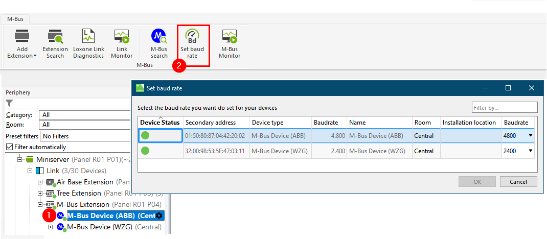
Change Baud Rate↑
Even if M-Bus devices work with different baud rates, they can be operated together.
If necessary, the baud rate of M-Bus devices can be changed in LOXONE Config:
Diagnostic Inputs↑
| Summary | Description | Unit | Value Range |
|---|---|---|---|
| Online Status M-Bus Extension | Indicates whether the device can be reached by the Miniserver. Diagnostics for Air devices Diagnostics for Tree devices Diagnostics for Extensions | Digital | 0/1 |
Properties↑
| Summary | Description | Default Value |
|---|---|---|
| Serial number | Specifies the serial number of the device. Enter 'Auto' to automatically pair an Extension with unknown serial number. This can only be used if there is only one Extension of the same type on a standalone Miniserver (not in a Client-Gateway setup). Save in the Miniserver to pair the Extension. Afterwards the program must be loaded from the Miniserver to transfer the actual serial number of the Extension into the program. | - |
| Monitor online status | If checked, you will be notified via System Status or the Mailer if the device is no longer available or goes offline. | - |
Safety Instructions↑
Installation must be carried out by a qualified electrician in accordance with the applicable regulations.
This device must be mounted on a DIN rail in an electrical distribution enclosure to ensure protection against contact, water and dust.