This block controls fan coil units with fresh air supply, commonly used in commercial buildings and hotels.
Depending on the current room temperature (ϑc), target temperature (ϑt), and CO2 level (CO2), the air volume and valves are regulated.
The regulation depends on the operating state and is controlled via a PI controller based on temperature or air quality.
Table of Contents
Inputs↑
| Abbreviation | Summary | Description | Unit | Value Range |
|---|---|---|---|---|
| ϑc | Current Room Temperature | Value will be provided by connected Intelligent Room Controller. If the input is also used, the most recent change applies. | ° | ∞ |
| ϑt | Target Room Temperature | Value will be provided by connected Intelligent Room Controller. If the input is also used, the most recent change applies. | ° | ∞ |
| Ha | Heating Available | Confirmation that heating energy is available at this unit. Use either standalone (e.g. heat pump "ready", boiler enable) or alongside a Fan Coil Central Controller as a local check that warm water has reached the unit (transit-time protection). TRUE / not connected: heating may run on demand. FALSE: heating output forced off, prevents cold air being blown into the room. If assigned to a Central Controller: AND-combined with the central controller's information. | - | 0/1 |
| Ca | Cooling Available | Confirmation that cooling energy is available at this unit. Use either standalone (e.g. chiller "ready") or alongside a Fan Coil Central Controller as a local check that chilled water has reached the unit (transit-time protection). TRUE / not connected: cooling may run on demand. FALSE: cooling output forced off, prevents warm air being blown into the room. If assigned to a Central Controller: AND-combined with the central controller's information. | - | 0/1 |
| CO2 | Current Room CO2 | Value will be provided by connected Intelligent Room Controller. If the input is also used, the most recent change applies. | ppm | 0...∞ |
| Dwc | Door and Window Contact | 0 = Closed 1 = Open | - | 0/1 |
| Rtd | Reset to default | Resets parameters and settings of the block to the default values as specified in the block preset. | - | 0/1 |
| Off | Off / Lock | Pulse (< 200 ms): Turns Fan and Valves Off. Pulse (> 200 ms): All outputs are switched off, timers are reset and block is locked. Dominating input. | - | 0/1 |
| Sm | Silent Mode | When activated, maximum fan speed is set according to the "Silent Mode Fan Speed" setting. When deactivated again, the fan speed will be recalculated. | - | 0/1 |
| Bm | Boost Mode | Sets fan speed to maximum. | - | 0/1 |
| Pt | Pause Timer | Pauses the device for the duration set in parameter (Ptd). | - | 0/1 |
| Fan | Fan Speed | Fan speed in percentage of full power. -1 for Auto. -1 if not connected. | % | -1...100 |
Parameters↑
| Abbreviation | Summary | Description | Unit | Value Range | Default Value |
|---|---|---|---|---|---|
| CO2t | Target CO2 | CO2 air quality threshold. If the CO2 value exceeds this threshold, air quality is considered bad and the logic changes according to the table below. | ppm | 0...∞ | 600 |
| Fmax | Maximum Fan Speed in Auto Mode | % | 0...100 | 80 | |
| Mode | Mode | 0 = Off 1 = Auto 2 = Heating 3 = Cooling 4 = Ventilation If set to Auto and controlled by IRC, it will be set by IRC | - | 0...4 | 1 |
| Ptd | Pause Timer Duration | Starts with the rising edge of input (Pt). Keeps the device paused for the specified duration. | s | 0...∞ | 7200 |
| FϑKP | Proportional Gain (Fan Temp) | Proportional Gain for Fan output based on Temperature. Used for PI Controller. | - | 0...∞ | 50 |
| FϑKI | Integral Gain (Fan Temp) | Integral Gain for Fan output based on Temperature. Used for PI Controller. | - | 0...∞ | 0.01 |
| FϑSt | Sample Time (Fan Temp) | Sample Time for Fan output based on Temperature. Used for PI Controller. | s | 0...∞ | 60 |
| Fco2KP | Proportional Gain (Fan CO2) | Proportional Gain for Fan output based on Air quality (CO2). Used for PI Controller. | - | 0...∞ | 50 |
| Fco2KI | Integral Gain (Fan CO2) | Integral Gain for Fan output based on Air quality (CO2). Used for PI Controller. | - | 0...∞ | 0.01 |
| Fco2St | Sample Time (Fan CO2) | Sample Time for Fan output based on Air quality (CO2). Used for PI Controller. | s | 0...∞ | 60 |
| VKP | Proportional Gain (Valve) | Proportional Gain for Valve outputs based on Temperature. Used for PI Controller. | - | 0...∞ | 50 |
| VKI | Integral Gain (Valve) | Integral Gain for Valve outputs based on Temperature. Used for PI Controller. | - | 0...∞ | 0.01 |
| VSt | Sample Time (Valve) | Sample Time for Valve outputs based on Temperature. Used for PI Controller. | s | 0...∞ | 60 |
Outputs↑
| Abbreviation | Summary | Description | Unit | Value Range |
|---|---|---|---|---|
| H | Heating Output | - | 0...10 | |
| C | Cooling Output | - | 0...10 | |
| HC | Combined Heating/Cooling Output | - | 0...10 | |
| Fan | Fan Speed Analogue | - | 0...100 | |
| FanS | Fan Speed Step | Current step calculated with "Fan Speed Steps" setting. | - | 0...∞ |
| ϑc | Current Room Temperature | ° | ∞ | |
| ϑt | Target Room Temperature | ° | ∞ | |
| Mode | Current Mode | 0 = Off 1 = Auto 2 = Heating 3 = Cooling 4 = Ventilation | - | 0...4 |
| S | Status | On when either valve is open or fan is active. | - | 0/1 |
| API | API Connector | Intelligent API based connector. Can link several functions between devices and blocks. API Commands | - | - |
Properties↑
| Summary | Description | Unit | Value Range | Default Value |
|---|---|---|---|---|
| Fan speed steps | For mapping discrete steps. Example: 4 steps -> 25% of full power for each step. Setting it to 0 disables Fan Speed Step (FanS) output. | - | 0...100 | 3 |
| Silent mode fan speed | Maximum fan speed in silent mode | % | 0...100 | 10 |
Functional Description↑
This block regulates air volume as well as heating and cooling output based on current temperature, target temperature, and air quality (CO2).
Humidity is not considered.
The air volume is only increased as necessary to maintain the target temperature and air quality, as larger air volumes lead to higher energy losses.
The outputs are controlled according to the following operating logic:
| Operating Mode | Air Volume | Heating Output | Cooling Output |
|---|---|---|---|
| Heating & Good Air Quality | ϑ variable | 100 % | 0 % |
| Heating & Bad Air Quality | CO2 variable | ϑ variable | 0 % |
| Cooling & Good Air Quality | ϑ variable | 0 % | 100 % |
| Cooling & Bad Air Quality | CO2 variable | 0 % | ϑ variable |
| Bad Air Quality | CO2 variable | 0 % | 0 % |
| Everything OK | 0 % | 0 % | 0 % |
ϑ variable
The air volume is adjusted depending on the difference between current temperature and target temperature.
The heating or cooling output operates at full capacity.
CO2 variable
The air volume is adjusted based on air quality.
If the air quality worsens, the air volume is increased.
Heating and cooling output are adjusted to fit the current demand.
 | To ensure stable and non‑disruptive control, the air volume is adjusted once per minute, with changes limited to a maximum of 20%. As a result, a full adjustment from 100% to 0% requires five minutes. For example, if the air quality worsens in the Heating & Good Air Quality mode, the air volume regulation is gradually switched from temperature-based to CO2-based control. |
Programming Example↑
Combination with Intelligent Room Controller
The heating and cooling valves as well as the fan are connected to the corresponding outputs of the block.
The Fan Coil Fresh Air Unit Controller can be connected to the Intelligent Room Controller via the API Connector:
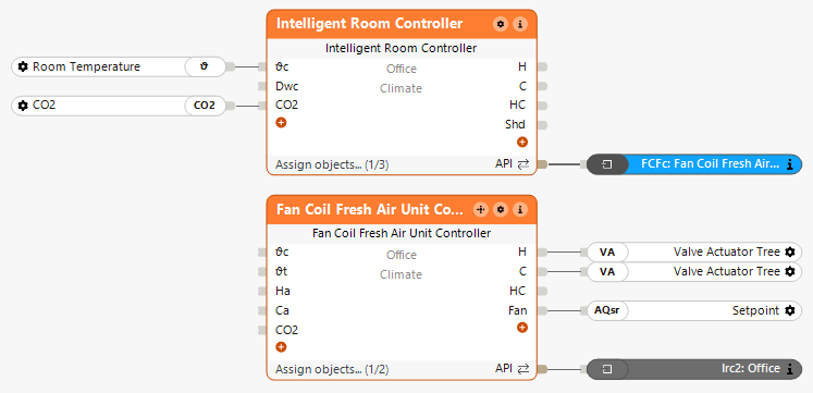
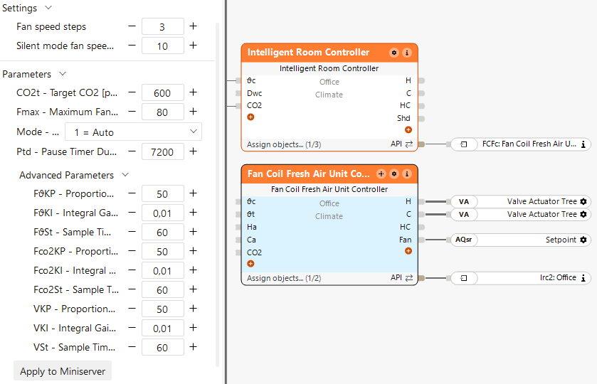
In the properties window, the PI controller parameters for the temperature-based fan regulation, CO2-based fan regulation, and temperature-based valve regulation can be adjusted.
Since this example uses a 4-pipe system, the inputs (Ha) and (Ca) do not need to be connected, as heating and cooling are assumed to be available by default.
The Intelligent Room Controller handles the room logic and passes temperature values and heating/cooling requirements to the Fan Coil Fresh Air Unit Controller.
This adjusts the air volume and heating/cooling valves while considering air quality.
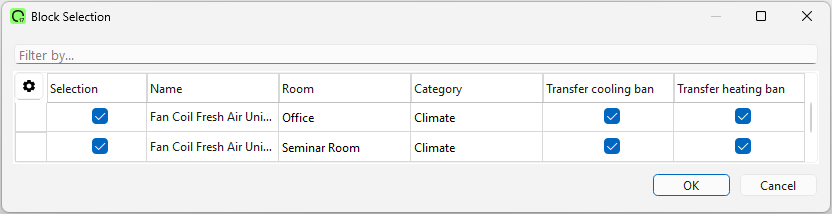
Combination with Intelligent Room Controller and Fan Coil Central Controller
By double-clicking the central block, the corresponding Fan Coil Fresh Air Unit Controllers can be added:
In the properties window, the system type (2-pipe or 4-pipe) can be selected directly:
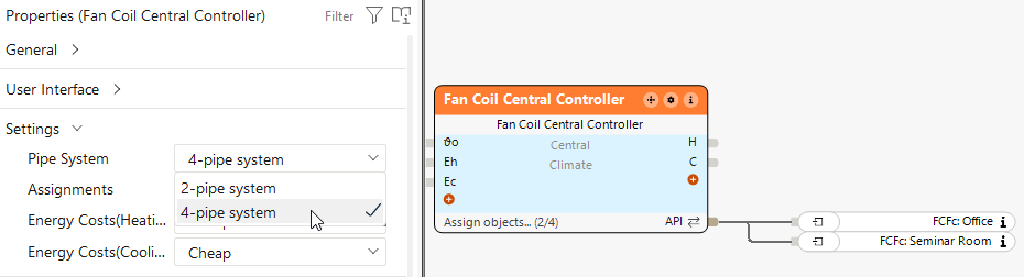
The Fan Coil Central Controller gathers the demands and decides between heating and cooling.
Based on this decision, the Fan Coil Fresh Air Unit Controllers adjust the valves and air volume in the respective rooms, considering air quality.
This block can also operate standalone. In this case, temperature values and CO2 levels are passed directly to the block via the inputs.