The Miniserver Compact serves as a central control unit for all kinds of automation tasks.
Interfaces for Link, Tree, Air and Tree Turbo are integrated for expansion with numerous devices.
The Miniserver Compact also serves as an Audioserver.
The USB interface can be used to connect storage devices with music files.
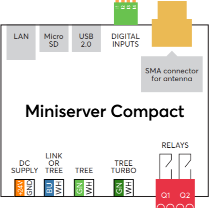
The replaceable microSD card contains the operating system as well as the user programming and settings. The LAN interface is used for programming and the integrated web server allows the control of the system via a web interface or the LOXONE App (up to 63 simultaneous connections). The USB interface can be used to connect storage devices with music files.
It features 2 dry relay contacts, 4 digital inputs. Up to 30 Extensions can be added to the Miniserver via the Link interface to add additional functions such as inputs, outputs or interfaces.
A Loxone Tree interface is also integrated to connect sensors and actuators throughout the building.
An Air Base Extension for connecting devices via Loxone Air wireless technology is already integrated.
Using the Tree Turbo interface, every Audioserver can be expanded with Tree Turbo Audio devices for additional zones or speaker outputs. For larger systems, multiple Audioservers can be used.
Datasheet Miniserver Compact up to serial number 504F94D1100C
Table of Contents
- Mounting
- Commissioning
- Connecting Extensions
- Connecting Tree Devices
- Tree Turbo
- Pairing Air Devices
- Loxone Health Check
- Device Status
- LED Status
- Replace Miniserver
- Inputs, Outputs, Properties
- Safety Instructions
- Documents
Mounting↑
The Miniserver is installed on a DIN rail in a suitable enclosure.
 | Installation Environment Requirement The Miniserver configuration may contain sensitive data, such as phone numbers and email addresses. To protect this information, the Miniserver must be installed in a secure location with restricted access, ensuring that only authorized personnel can physically reach the device. Suitable installation locations include locked electrical enclosures or secured technical rooms. |
 | The Miniserver Compact and Air signals can negatively influence each other when in close proximity. Therefore, a distance of 2 division / breaker units should be maintained between a Miniserver Compact and an Air Base. |
Connect the power supply, as well as needed inputs and outputs, or devices on the different interfaces.
The Link Interface (blue/white terminal) can also be switched to a Tree Interface in Loxone Config.
Via the LAN port the Miniserver is connected to the local network or a WiFi router.
 | Mains and SELV/PELV must not be connected to relay output at the same time. |
Commissioning↑
The Miniserver starts after the power supply is turned on, and will be operational within a few seconds.
Once the boot up process is complete, the left status LED will blink green once every second.
The right LED indicates whether any System Status messages are available.
At first startup with factory settings, the Miniserver is assigned an IP address by the router via DHCP.
If there is no DHCP server in your network, or if the Miniserver is connected directly to a PC, link-local addressing via Zeroconf is supported.
If both Miniserver and computer are set to DHCP, they will use a 169.254.x.x link-local address.
Alternatively, you can manually assign a static IP address to the Miniserver and computer to enable a direct connection.
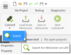
You can then search for the Miniserver in Loxone Config and connect. The factory settings for user and password are: admin/admin
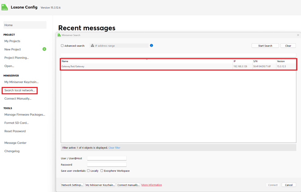
Then follow the instructions for the Initial Setup to create your new project with the Miniserver.
Connecting Extensions↑
Up to 30 Extensions can be connected to a Miniserver's Link interface according to the following diagram:
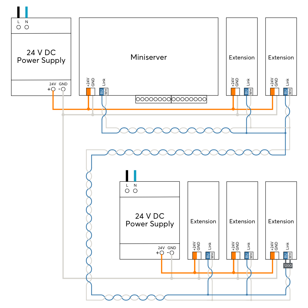
Connect the Extensions to a Miniserver by daisy-chaining the Link interfaces. If any of the Extensions are connected to a separate power supply, then all power supply's GND (negative) have to be interconnected. This connection is crucial for reliable data transmission.
The blue/white wires are used to wire the Link throughout a building. This allows a maximum length of 500m/1640ft.
The Link interface is terminated at the last Extension using the 120 Ohm resistor that is included with the Miniserver.
After switching on the power supply, the Extensions first flash red, and after successful connection to the Miniserver they flash orange.
You can now proceed with pairing the Extensions.
Connecting Tree Devices↑
Up to 50 Tree Devices can be connected to the Tree interface of a Miniserver, or each of the two Branches of a Tree Extension. There must be no connection between different Tree Branches.
The following diagram shows the wiring of several Tree devices connected to two different Branches of a Tree Extension.
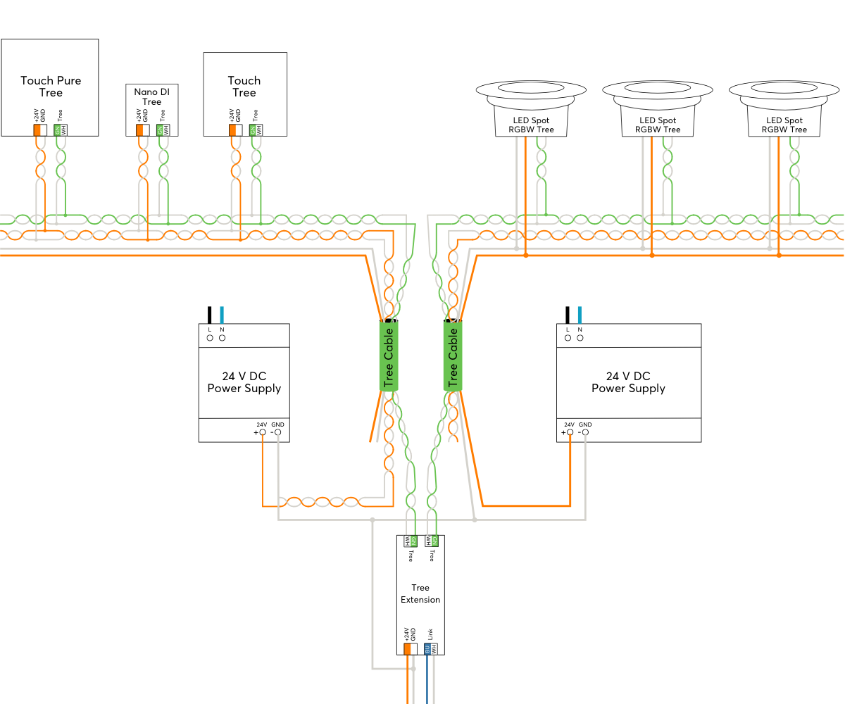
The following wiring topologies are possible, at a maximum length of 500m/1640ft:

The Loxone Tree Cable is used for wiring, it contains the Tree communication lines as well as the lines for the 24VDC power supply in the corresponding colors. For devices with higher power requirements such as Tree lighting products, the Tree Cable also contains a pair of wires with 1.5mm² cross-section (AWG16) for power supply.
We recommend running one Tree Cable from the panel per room and then branching off to the individual Tree devices in that room. This corresponds to a Tree topology.
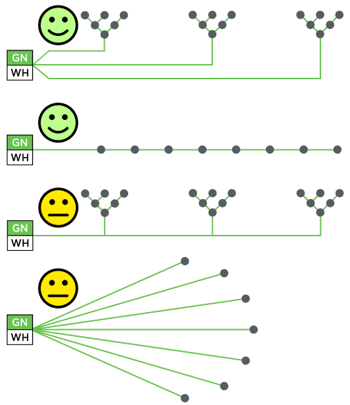
The following image illustrates favorable and less favorable wiring structures within a building, based on the permitted topologies:
Within the enclosure, panel wire with twisted pairs is used for wiring.
Devices that communicate with each other have to share a common GND. This is necessary if more than one power supply is used. (e.g. in a sub-panel, or if separate power supplies are used for lighting). For this all power supply's GND (negative) have to be interconnected. This connection is crucial for reliable data transmission.
The cable length of max. 500m per tree branch refers purely to the data lines, not to the 24V power supply. For consumers with higher power such as tree lamps or tree dimmers, the achievable cable length is often significantly shorter due to the resulting voltage drop.
If the current flow on the GND line results in a voltage drop too high, this potential difference also affects the tree communication.
To solve this problem, split consumers of higher power over longer distances to several supply lines, or use a supply line with a higher cross-section, or a power supply close to the consumers.
For existing installations, doubling the cross-section of the GND line is often sufficient to eliminate the potential difference.
You can now proceed with pairing the Tree devices.
Tree Turbo↑
For Tree Turbo wiring and topology, pairing, and speed requirements, see the Tree Turbo Interface documentation.
Pairing Air Devices↑
Pairing Mode
All Air devices have to be paired in Loxone Config via the pairing mode. In delivery state, pairing mode will be active after the power supply has been established.
On most Air devices, the status LED will indicate this by blinking red/green/orange. You can find the exact method of indicating pairing mode in the documentation of the respective Air device.
On most battery powered Air devices the pairing mode is only active for 5 minutes to conserve energy. Briefly remove the battery and then reinsert it to reactivate pairing mode, if necessary.
If an Air device blinks only orange, then it was previously paired, but can no longer establish a connection. In this case, you have to activate the pairing mode manually. On most devices, this is done by pressing the pairing button or power cycling the device.
Searching and pairing
To search for Air devices, first click on an Air interface in Loxone Config, and then activate Air Device Search
The window that opens will list all Air devices that are in pairing mode. This can take a few minutes:
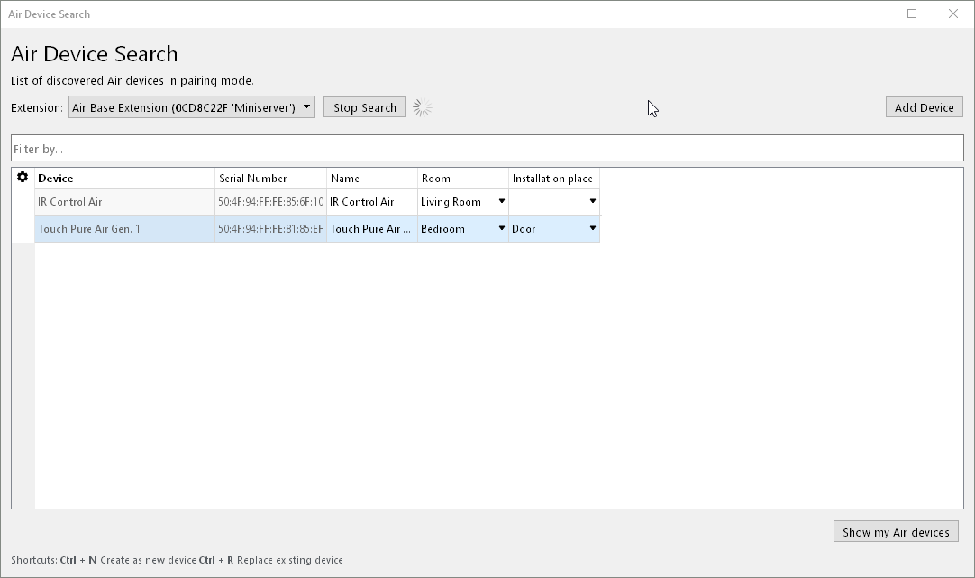
If you select a device here, it will identify itself in different ways. Devices with a status LED will flash it, lighting products pulse a white light, other devices such as the Loxone Touch emit an audible click. This allows you to assign and name the devices correctly.
Select the desired device, assign a name, room and installation location and add it to the programming using the Pair Device or + button.
The right window lists all the devices that are currently part of the program. You can display them by clicking the button Show my Air devices. You can also replace an existing device with a new device of the same type that was found in the search. This is useful when a device needs to be replaced or devices are added to a pre-configured program. Select the device to be added and the device to be replaced. By clicking on the button with the arrow pointing right, the old device is replaced with the new one in the program.
To apply the changes, save the program in the Miniserver.
Now the added devices are ready for use and the functions are available in the Periphery Tree in Loxone Config.
The LOXONE App, under Settings, also supports searching for and pairing Air devices.
Loxone Health Check↑
The diagnostics of the Miniserver and the Loxone interfaces can be started via the Loxone Health Check:

Device Status↑
The Device Status serves as a central overview of the status of all devices in the programming, This enables a fast, but also detailed error diagnosis.
The Device Status can be opened via the menu bar:

If a device is offline, currently being updated or has not yet been paired, this is highlighted in color in the status column:

Diagnostic Options
With a right click on the desired device, individual information can be retrieved and actions triggered. These available options are device-dependent.
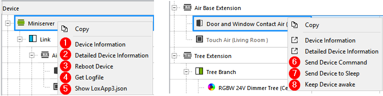
1. Text file with details of the selected device
2. Detailed troubleshooting details are summarized in a text file (TechReport), battery powered air devices must be awake for this purpose
3. Reboot device*
4. Get central log file def.log, where important events in the system are logged*
5. Show structure file LoxApp3.json, file to enable communication between user interface and Miniserver*
6. Send device command
7. Send device to sleep
8. Keep device awake
* only available for Miniserver
Additional information
Update and Diagnostics for Tree Devices
Update and Diagnostics for Air Devices
LED Status↑
| Left LED | Right LED | Description |
|---|---|---|
|
| Everything OK, device is online. |
|
| One or more System Status messages are active. |
|
| Device was selected in Loxone Config and is identifying. |
|
| Update is in progress. |


Boot Phase:
| Left LED | Right LED | Description |
|---|---|---|
|
| Miniserver is booting. |
|
| Miniserver is loading the bootloader image from the SD card. |
|
| Miniserver has successfully loaded the image and will unpack it as the next step. |
|
| Miniserver has successfully unpacked the image. |
|
| Operating system is started. |
|
| Miniserver is loading the program file. |
|
| SD card cannot be read. Check SD card. |
|
| No compatible operating system on the SD card. |


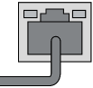
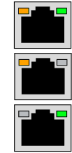
| RJ45 Port | Description |
|---|---|
| Network connection |
| No network connection |
| Indicates data traffic |
| If one or both LEDs are permanent on without a plug connected, this indicates that the interface is damaged. |
Replace Miniserver↑
If a Miniserver needs to be replaced by another one, a wizard is available in Loxone Config to guide you through the necessary steps.
Start the wizard and follow the instructions:

Sensors↑
| Summary | Unit | Value Range |
|---|---|---|
| Input 1 | Digital | 0/1 |
| Input 2 | Digital | 0/1 |
| Input 3 | Digital | 0/1 |
| Input 4 | Digital | 0/1 |
Actuators↑
| Summary | Unit | Value Range |
|---|---|---|
| Actuator (Relay) 1 | Digital | 0/1 |
| Actuator (Relay) 2 | Digital | 0/1 |
Diagnostic Inputs↑
| Summary | Description | Unit | Value Range |
|---|---|---|---|
| Computing power throttling | Indicates whether the device can be reached by the Miniserver. Diagnostics for Air devices Diagnostics for Tree devices Diagnostics for Extensions | Digital | 0/1 |
| Temperature Shutdown | Input is active, when the outputs of the device have been switched off due to high device temperature. Possible reasons: Ambient temperature too high, outputs overloaded. | Digital | 0/1 |
Properties↑
| Summary | Description | Default Value |
|---|---|---|
| Serial Number | Specifies the serial number of the device. | - |
| Local Address | Enter the local address of the Miniserver, this is the IP address or hostname that can be used to reach it on the local network. Hostnames are not supported in Gateway-Client projects. | - |
| External Address | Enter the address at which the Miniserver is accessible via the internet (hostname or IP address). If you are using Loxone Cloud DNS, then please enter connect.loxonecloud.com or connect.loxonecloud.com:<port> if not using default port 80. | - |
| External Port HTTP | The external port that you specified in the port forwarding settings of your router for the HTTP port of the Miniserver | - |
| External Port HTTPS | The external port that you specified in the port forwarding settings of your router for the HTTPS port of the Miniserver | - |
| Miniserver Configuration | Edit Miniserver settings. A connection to the Miniserver is required. | - |
Safety Instructions↑
Installation must be carried out by a qualified electrician in accordance with the applicable regulations.
This device must be mounted on a DIN rail in an electrical distribution enclosure to ensure protection against contact, water and dust.
Documents↑
Datasheet Miniserver Compact up to serial number 504F94D1100C