This compact, DIN rail-mounted, MID-certified energy meter enables bidirectional measurement using three external 40 mA current transformers of your choice. It offers instant power outage detection and is ideal for energy management and monitoring in residential and commercial settings.
Datasheet Energy Meter for 40mA Current Transformers Tree
Table of Contents
- Mounting
- Commissioning
- Programming
- Single phase metering
- Additional Sensors
- Display
- Net Metering
- LED Status
- Current Transformer Connection
- Accuracy of Current Transformers
- Inputs, Outputs, Properties
- Safety Instructions
- Documents
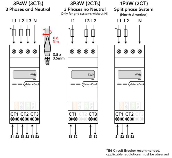
Mounting↑
The meter must be connected in accordance with the grid system at the installation site:
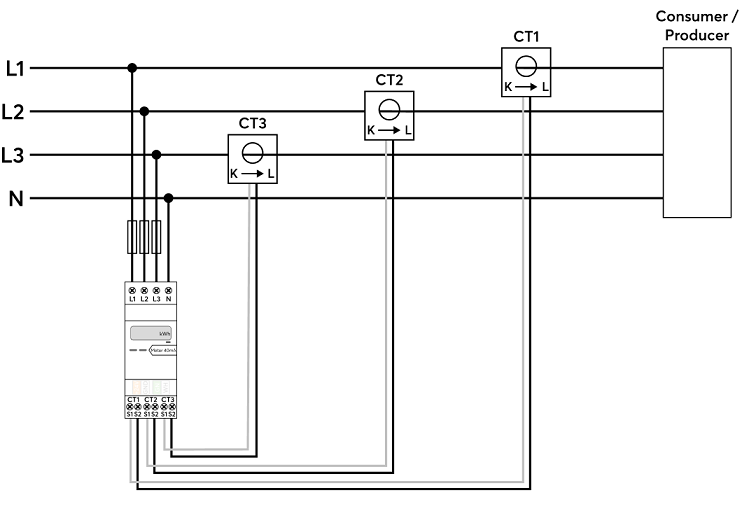
When using Loxone current transformers, follow the connection diagram below:
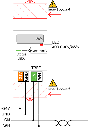
After connecting the mains lines, the covers must be placed over the mains terminal blocks, followed by connecting the Tree and 24V lines.
Commissioning↑
For commissioning, the device must be supplied with power and a connection to the Miniserver must be possible via the Tree Interface.
Then follow the pairing procedure on the Tree Interface.
Programming↑
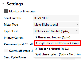
After pairing the meter, the "Meter Type", "Type of use", as well as the "Primary Current" must be selected.
Subsequently, the meter can be dragged to the programming page. This action automatically creates the Meter Block:
 | In the Primary Current setting of the Energy Meter, always enter the rated primary current of the connected current transformers (e.g., 25A when using 25A CTs). When "Permanently set CT ratio" is selected, the Energy Meter locks the configured ratio to ensure compliance with legal metrology standards (e.g., MID) and to guarantee accurate billing. Once set, the ratio can no longer be modified. |
By default, the API Connector transmits the meter reading and power at the following intervals:
Power: Every 5 seconds, but only on value change.
Meter readings: Every 60 seconds, but only on value change. The transmission cycles can be individually configured in the device settings.
Alternatively, sensors can be manually inserted, and their polling cycle can be set. These are then used at the inputs of the meter block instead of the API Connector.
Single phase metering↑
Single phase metering is a preset that provides separate energy meter blocks for each phase. This allows for individual consumers or rooms on different phases to be separately tracked in a sub-distribution panel.
This setting can be selected after pairing the meter and is only available for the 3P4W grid system:
For the 1P3W grid system, single-phase metering can be implemented by manually adding sensors.
For the 3P3W grid system, single-phase metering is not possible in general.
Additional Sensors↑
The meter provides additional measurements through analog sensors that must first be added. Afterward, the desired measurement is selected:
The number of available sensors depends on the "Meter Type" and the configured "Type of use".
Total Active Power and Total Meter Reading Consumption/Delivery are not visible in this list, as these values are transmitted via the API connector.
Display↑
The display alternately shows the following values:

If the option "Permanently set CT ratio" is selected, this will also be indicated on the display.
Net Metering↑
In the 3P4W setting, the meter operates on a net basis. This means, that the total values are formed by summing the power across all phases.
When the overall power is positive, energy is consumed, and thus added to the consumption meter reading (Mrc).
When the overall power is negative, energy is delivered, and thus added to the delivery meter reading (Mrd).
When the ratio between delivered and consumed power is equal, the total power is zero. In such moments, neither of the total meter readings increases.
This netting is also widespread among meters used by energy providers.
LED Status↑
| Status LED | Description |
|---|---|
| Everything OK, device is online. |
| Connection to the Miniserver is okay, but the device has not been paired. |
| Device cannot connect to the Miniserver via the Tree interface. |
| Device was selected in Loxone Config and is identifying. |
| Update is in progress. |
| The connection to the Miniserver is established, but no AC mains voltage is detected. |
| Internal device communication error |


Current Transformer Connection↑
The correct connection of the current transformers and their assignment to the correct phases is essential for accurate measurements.
Reversing the polarity (black and white swapped) or installing a transformer in the wrong orientation will cause the energy flow on that phase to reverse. The measured power for the phase will still be correct in magnitude, but its sign will be inverted.
Incorrect wiring of the current transformers is often less obvious. This can result in distorted power measurements, including significant deviations from actual values or even reversal of the measured power flow direction.
Accuracy of Current Transformers↑
When using current transformers (CTs), always refer to the datasheet to ensure measurements fall within the CTs specified voltage and current ranges for accurate readings.
Loxone Energy Meters:
Energy Meter for 1A & 5A CTs
200A CT: 10A minimum, 240A maximum
400A CT: 20A minimum, 480A maximum
Energy Meter for 40mA CTs
25A CT: 1.25A minimum, 30A maximum
100A CT: 5A minimum, 120A maximum
Sensors↑
| Summary | Description | Value Range |
|---|---|---|
| Voltage loss detected | Indicates a detected voltage loss on L1. The meter checks for loss every 5 seconds and triggers if detected. Loss detection is only available on L1; L2 and L3 failures must be inferred from power/voltage variations. | 0/1 |
Actuators↑
| Summary | Description |
|---|---|
| API Connector | Intelligent API based connector. API Commands |
Diagnostic Inputs↑
| Summary | Description | Unit | Value Range |
|---|---|---|---|
| Online Status Energy Meter 1-Phase Tree | Indicates whether the device can be reached by the Miniserver. Diagnostics for Air devices Diagnostics for Tree devices Diagnostics for Extensions | Digital | 0/1 |
Properties↑
| Summary | Description | Value Range | Default Value |
|---|---|---|---|
| Monitor Online Status | If checked, you will be notified via System Status or the Mailer if the device is no longer available or goes offline. | - | - |
| Serial Number | Specifies the serial number of the device. Enter 'Auto' to automatically pair a Tree device with unknown serial number. This can only be used if there is only one Tree device of the same type on a standalone Miniserver (not in a Client-Gateway setup). Save in the Miniserver to pair the Tree device. Afterwards the program must be loaded from the Miniserver to transfer the actual serial number of the Tree device into the program. | - | - |
| Meter Type | Choose which type of Meter Function Block you want to insert. Meter: only one energy direction is monitored. Meter Bidirectional: both energy directions are monitored. Meter for Storage: for use with Batteries, bidirectional with charge Level. Wallbox: for use with EV Charging Wallboxes. | - | - |
| Type of use | Selection of Grid System and Single-Phase metering. 3 Single Phases and Neutral (3p4w): Provides a separate meter block for each of the three phases. | - | - |
| Primary Current | Rated current on the primary side. Supported range: 5 A to 9999 A | ∞ | 1 |
| Permanently set CT ratio | Permanently sets the current transformer ratio in the Energy Meter to comply with legal metrology standards (e.g. MID) and ensure accurate billing. Once set, the ratio cannot be modified. | - | - |
| Switch off status LEDs | If checked, the status LEDs on the device are switched off in normal operation. In the event of a fault, the device will continue to alert you to its status LEDs. | - | - |
| Transmission cycle power [s] | Minimum transmission cycle for power values via API actor. Values are updated only when they change. | 0.1...4095 | 5 |
| Transmission cycle energy [s] | Minimum transmission cycle for energy values via API actor. Values are updated only when they change. | 0.1...4095 | 60 |
| Monitor validation | If checked, you will be notified via System Status or Cloud Mailer when the value is out of the set range or at timeout. | - | - |
Safety Instructions↑
Installation must be carried out by a qualified electrician in accordance with the applicable regulations.
This device must be mounted on a DIN rail in an electrical distribution enclosure to ensure protection against contact, water and dust.
The selection of conductor cross-sections and associated overcurrent protection devices is dictated by national and international standards and installation guidelines. This requires choosing a conductor cross-section suitable for the loads rated current, as well as considering the insulation material of the cable, method of installation, and ambient temperature.
Documents↑
Datasheet Energy Meter for 40mA Current Transformers Tree
Datasheet 40mA Current Transformers 100A 16mm
Datasheet 40mA Current Transformers 25A 10mm