The Loxone Wallbox is a charging station which enables dynamic charging from 4.1 kW to 22 kW for electric vehicles.
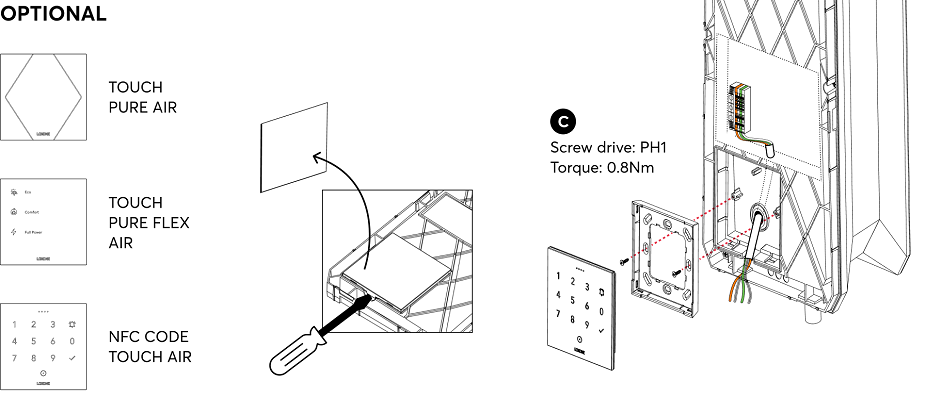
With the robust Tree interface, the device is fully integrated into the Loxone system, providing complete freedom for energy management. The pre-installed Loxone Energy Meter 3-Phase Tree allows precise measurement of electrical energy and seamless communication with the system. Optionally, devices such as the NFC Code Touch, Touch Pure Flex, etc., can be directly mounted on the Wallbox for setting the charging mode or executing other smart control functions.
Datasheet Wallbox 22kW 32A Tree
Table of Contents
- Mounting
- Commissioning
- Programming
- LED Status
- Charging Cable
- Limiting charging power
- Testing the Wallbox
- Modbus Data Reading
- Wallbox Error Codes
- Inputs, Outputs, Properties
- Safety Instructions
- Documents
Mounting↑
Attach the Wallbox vertically by screwing it onto a solid, even and closed surface.
Select screws and fastening material according to the surface.
Make sure that the mounting frame rests flush on the surface without any gaps.
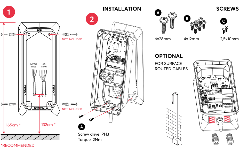
After mounting, the supply voltage (mains voltage and 24V) is switched on, the Wallbox flashes orange after a short time if the connection to the Miniserver is successful and is ready for pairing.
Note: Do not install the Wallbox using magnets or place it near magnetic sources (closer than 0.5 meters). Magnetic fields may interfere with the internal residual current device, potentially affecting the charging functionality.
Commissioning↑
Then follow the pairing procedure on the Tree Interface.
After pairing the Wallbox, right-click on the device and select "Show installed meter" to view the serial number of the associated energy meter:
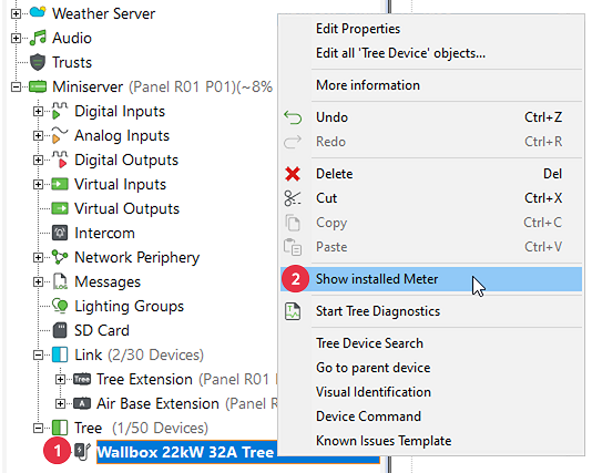
The pre-installed energy meter can now be paired via serial number or Tree device search.
Programming↑
The Loxone Wallbox is programmed and set up using the Wallbox function block in Loxone Config:
After pairing the meter, the Meter Type "Wallbox" and the Wiring direction "Inverted (Top = Out)" must be selected.
The meter can then be dragged onto the Wallbox function block to link it:
LED Status↑
| Status LED | Description |
|---|---|
| Device has just been paired or has restarted and is now online. |
| Connection to the Miniserver is okay, but the device has not been paired. |
| Device cannot connect to the Miniserver via the Tree interface. |
| Device was selected in Loxone Config and is identifying. |
| Charging started. |
| Charging paused. |
| Charging Error. |


Charging Cable↑
If it is necessary to replace the charging cable, this must be installed and tested by a specialist in accordance with national regulations.
For this purpose, a charging cable with the same properties must be used; this may also be shorter or longer (max. 7.5 meters).
Extending the charging cable in any other way is not permitted.
Limiting charging power↑
The Loxone Wallbox is able to limit the charging power by transmitting the permitted maximum current to the vehicle.
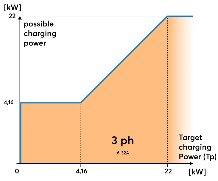
The actual charging power depends on the vehicle, supply voltage, and battery level, and may be above or significantly below the target charging power (Tp).
Testing the Wallbox↑
Note on testing the Wallbox with EVSE Testers:
Due to the testing of the internal residual-current sensor, a waiting period of at least 10 seconds is required when switching from Position B (vehicle connected) to Position C (vehicle ready to charge). Also, charging power for the charging process must be authorised to the wallbox. Otherwise, an unknown charging error may occur.
Modbus Data Reading↑
Only the values that are actually sent to the Miniserver are displayed in the Modbus Monitor.
This means that only values that have changed are shown. The data is not displayed in the monitor with every polling cycle.
Wallbox Error Codes↑
Error Code Transmission for Improved Diagnostics
To enhance error diagnostics, the Wallbox transmit error codes to the Miniserver. These codes are displayed in the System status messages.
Error Codes Overview:
| Code | Title | Description |
|---|---|---|
| 101 | Fault Current | A fault current was detected during operation. |
| 102 | RCD Init Timeout | The internal RCD did not complete initialization within the expected time. |
| 103 | RCD Test Timeout | The internal RCD did not respond during the self-test. |
| 104 | RCD Test Failed | The internal RCD self-test failed. |
| 105 | RCD Supply Fault | The power supply of the internal RCD dropped or is unstable. |
| 201 | Unexpected State | The EV entered an undefined or unsupported state during charging. |
| 202 | RCD Not Ready | The internal RCD is not ready for operation. |
| 203 | No Pilot Diode | Pilot diode was not detected in the vehicle. |
| 204 | Digital Communication | An unsupported digital communication standard was detected. |
| 205 | Ventilation Required | The EV requests external ventilation before charging can continue. |
| 206 | Phase Switching Timeout | After a phase switching event, the EV does not resume charging within the expected time. The charging process remains in a non-ready state. |
| 300 | Voltage Dip | A voltage dip in the power supply was detected. |
Diagnostic Inputs↑
| Summary | Description | Unit | Value Range |
|---|---|---|---|
| Charging error | Reports a charging error. | - | 0/1 |
| Fault current | Reports a fault current. | - | 0/1 |
| Online Status Wallbox 11kW 16A Tree | Indicates whether the device can be reached by the Miniserver. Diagnostics for Air devices Diagnostics for Tree devices Diagnostics for Extensions | Digital | 0/1 |
| System temperature | Provides the internal device temperature. This is often the temperature of the CPU or another location in the device. | ° | ∞ |
| Error Code | - | ∞ |
Actuators↑
| Summary | Description |
|---|---|
| API Connector | Intelligent API based connector. API Commands |
Properties↑
| Summary | Description | Default Value |
|---|---|---|
| Monitor Online Status | If checked, you will be notified via System Status or the Mailer if the device is no longer available or goes offline. | - |
| Serial Number | Specifies the serial number of the device. Enter 'Auto' to automatically pair a Tree device with unknown serial number. This can only be used if there is only one Tree device of the same type on a standalone Miniserver (not in a Client-Gateway setup). Save in the Miniserver to pair the Tree device. Afterwards the program must be loaded from the Miniserver to transfer the actual serial number of the Tree device into the program. | - |
Safety Instructions↑
Installation must be carried out by a qualified electrician in accordance with the applicable regulations.
Only mount on a solid, even and closed surface.
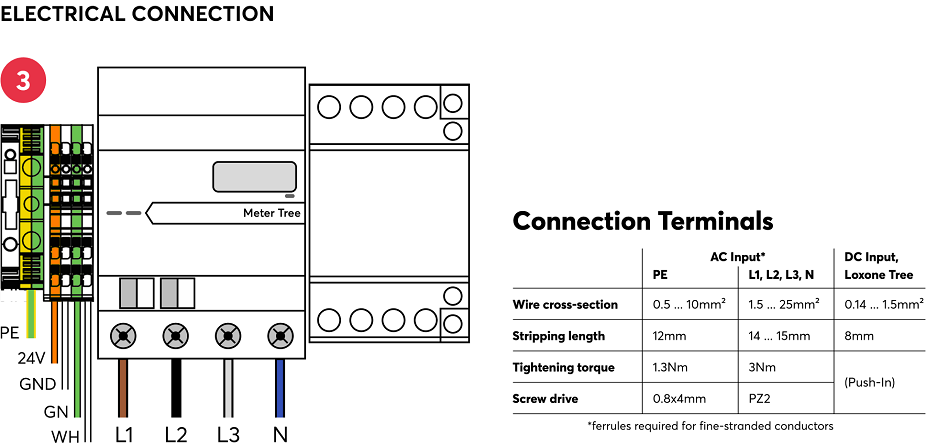
The selection of conductor cross-sections and associated overcurrent protection devices is dictated by national and international standards and installation guidelines. This requires choosing a conductor cross-section suitable for the loads rated current, as well as considering the insulation material of the cable, method of installation, and ambient temperature.
Documents↑
Datasheet Wallbox 22kW 32A Tree
Datasheet Energy Meter 3-Phase Tree