                                    array(24) {
  ["id"]=>
  int(10620)
  ["name"]=>
  string(27) "Retrofit ventilation system"
  ["slug"]=>
  string(27) "retrofit-ventilation-system"
  ["challenge"]=>
  string(803) "[THIS CONTENT IS AUTOMATICALLY TRANSLATED BY GOOGLE TRANSLATE] The Scala is a lively meeting place for artists and cultural workers from all over Switzerland and beyond. Since 2003, the Scala has had its home in the venerable “Ochsen”. The inn was built in 1583 and can therefore look back on 440 years of history. In addition to the actual event location, the project includes a bar and a restaurant.


The historical building structure, the attached restaurant, high visitor numbers and more require optimal ventilation of the rooms. Although the Scala had a ventilation system, the control system was defective.


The aim of the retrofit project was to preserve the historic building and equip it with suitable, efficient and, above all, intelligent ventilation control."
  ["solution"]=>
  string(5099) "[THIS CONTENT IS AUTOMATICALLY TRANSLATED BY GOOGLE TRANSLATE] In this retrofit project, a total of two mini servers take over the intelligent control of the ventilation and heating system (the separation was due to the spatial distance between the heating and ventilation system). The complete automation of the existing system could be achieved with just a few components: The CO2 measurement is carried out via room climate sensors, the actual control is carried out by various Belimo components. The existing frequency converters were integrated into the ventilation control and controlled with 0-10V.

The Scala's event calendar has been linked to Loxone so that the ventilation and heating can automatically carry out preparatory work before an event. The hall is therefore ready for its guests at the right time with the right room climate.


1. Air volume control:

The air volume control is implemented via fan optimizer programming (bad point control). This means that the air volume of the fans, supply air and exhaust air is regulated as required depending on the volume flow controllers or their pumped air volume.

The differential pressure sensors in the 3 ventilation devices can be seen as the actual value. The sum of the active air volumes via the volume flow controller is used as the setpoint. The air volume is calculated in the software.

An exception is the kitchen exhaust air. It was important to ensure that the amount of air in the exhaust air was controlled depending on the volume flow controller in the supply air so that there was always a negative pressure in the kitchen. Here too, the air volume of the volume flow controller in the supply air is used as a setpoint, with a defined shortfall.

Kitchen

The existing rotary switch (0/Auto/S1/S2) in the kitchen was retained. Depending on the position, this regulates the kitchen ventilation. The air volume of the volume flow controller can be individually adjusted for levels 1 and 2.

The fan is controlled according to the flap position.

bistro

The room climate sensor currently has no regulating effect. It currently only provides values. A later implementation for regulation is possible at any time.

room

The room climate sensor records temperature, humidity and air quality. If the air quality is poor, the ventilation is switched on (if it is not already running). The Belimo volume flow controllers are regulated to a setpoint (adjustable). The worse the air quality, the more the volume flow controllers are opened. In addition, the air volume can be increased or decreased manually.

bar

Analogue hall.

Duct exhaust air sensors

Belimo sensors are placed in the exhaust air ducts of the dining room, bistro, bar and in the shared exhaust air of the gallery and hall and measure temperature, humidity and air quality. The air quality of the exhaust air has the same effect as the air quality in the rooms. For example, if the bar's exhaust air duct sensor measures poorer air quality than the bar's room climate sensor, it takes control of the corresponding controller.

Air heater

The air heater pump and air heater valve are located in the attic. There is no bypass. If there is a need for thermal energy, not only is the air heater pump and the air heater valve activated, but a demand message is also sent to the mini server, which switches on the main pump.


2nd circuit network system (KVS)

Energy recovery (heating or cooling) is carried out by the KVS. The temperature sensor serves as frost protection. If it is colder than 2°C (adjustable), the bypass valve is constantly opened to ensure frost protection in the exhaust air.

The pressure switch is used to monitor the system. The pump is controlled via a 0-10V signal, depending on how much volume is available from the two heat recovery valves.

2.1 Icing protection regulation

The dew point determined is the setpoint for the sensor at the outlet of the KVS register in the supply air. As long as the dew point, which is determined in the respective exhaust air via the humidity and temperature, is above 0°C, the exhaust air register flow temperature is kept above 0°C with the help of the bypass valve. If the determined dew point temperature falls below 0°C, the outlet temperature is also maintained at exactly this value by constantly opening the bypass valve.

2.2 Delta-T control

The Belimo Energy Valve maintains a 2-3 K lower temperature in the exhaust air at the respective outlet of the KVS register than in the exhaust air. This ensures optimal heat transfer. The circulation pump is operated at constant pressure. The start sequence in the ERG case is selected depending on the temperature range in the two exhaust air devices.


3. Temperature control

Since these are event rooms and are also equipped with static heating (radiators), a constant supply air temperature control is recommended. This is also ideal for the kitchen."
  ["partner_quote"]=>
  string(0) ""
  ["partner_quote_name"]=>
  string(0) ""
  ["partner_quote_position"]=>
  string(0) ""
  ["more_info_url"]=>
  string(0) ""
  ["preview_image"]=>
  string(81) "https://portal.loxone.com/admin/wp-content/uploads/2023/12/1702551068-768x511.jpg"
  ["application_areas"]=>
  array(1) {
    [0]=>
    string(11) "ventilation"
  }
  ["tags"]=>
  array(0) {
  }
  ["project_type"]=>
  array(2) {
    [0]=>
    string(11) "hospitality"
    [1]=>
    string(8) "retrofit"
  }
  ["copyright"]=>
  NULL
  ["images"]=>
  array(6) {
    [0]=>
    array(2) {
      ["image"]=>
      string(82) "https://portal.loxone.com/admin/wp-content/uploads/2023/12/1702551068-1024x682.jpg"
      ["copyright"]=>
      string(6) "Scala "
    }
    [1]=>
    array(2) {
      ["image"]=>
      string(83) "https://portal.loxone.com/admin/wp-content/uploads/2023/12/1702551165-1024x576.jpeg"
      ["copyright"]=>
      string(0) ""
    }
    [2]=>
    array(2) {
      ["image"]=>
      string(83) "https://portal.loxone.com/admin/wp-content/uploads/2023/12/1702551263-1024x576.jpeg"
      ["copyright"]=>
      string(0) ""
    }
    [3]=>
    array(2) {
      ["image"]=>
      string(83) "https://portal.loxone.com/admin/wp-content/uploads/2023/12/1702551274-1024x576.jpeg"
      ["copyright"]=>
      string(0) ""
    }
    [4]=>
    array(2) {
      ["image"]=>
      string(83) "https://portal.loxone.com/admin/wp-content/uploads/2023/12/1702551291-1024x576.jpeg"
      ["copyright"]=>
      string(0) ""
    }
    [5]=>
    array(2) {
      ["image"]=>
      string(82) "https://portal.loxone.com/admin/wp-content/uploads/2023/12/1702551359-1024x574.png"
      ["copyright"]=>
      string(0) ""
    }
  }
  ["country"]=>
  string(2) "CH"
  ["city"]=>
  string(8) "Wetzikon"
  ["build_year"]=>
  string(4) "1583"
  ["square_meters"]=>
  string(0) ""
  ["account_data"]=>
  array(4) {
    ["id"]=>
    string(36) "e57e9022-34c0-46f5-bf75-e0cca1041a9e"
    ["name"]=>
    string(24) "Hustech Installations AG"
    ["website"]=>
    string(0) ""
    ["partner_website"]=>
    string(47) "/partner/8608-bubikon/hustech-installations-ag/"
  }
  ["conference"]=>
  string(4) "none"
  ["products"]=>
  array(7) {
    [0]=>
    array(2) {
      ["sku"]=>
      string(6) "100335"
      ["name"]=>
      string(10) "Miniserver"
    }
    [1]=>
    array(2) {
      ["sku"]=>
      string(6) "100277"
      ["name"]=>
      string(64) "Room Comfort Sensor Tree Anthracite (CO2, Temperature, Humidity)"
    }
    [2]=>
    array(2) {
      ["sku"]=>
      string(6) "100519"
      ["name"]=>
      string(11) "Belimo Tree"
    }
    [3]=>
    array(2) {
      ["sku"]=>
      string(6) "100124"
      ["name"]=>
      string(16) "Modbus Extension"
    }
    [4]=>
    array(2) {
      ["sku"]=>
      string(6) "100471"
      ["name"]=>
      string(12) "AI Extension"
    }
    [5]=>
    array(2) {
      ["sku"]=>
      string(6) "100382"
      ["name"]=>
      string(12) "AO Extension"
    }
    [6]=>
    array(2) {
      ["sku"]=>
      string(6) "100283"
      ["name"]=>
      string(12) "DI Extension"
    }
  }
  ["video"]=>
  string(0) ""
  ["fallback"]=>
  array(8) {
    ["name"]=>
    string(27) "Retrofit ventilation system"
    ["challenge"]=>
    string(803) "[THIS CONTENT IS AUTOMATICALLY TRANSLATED BY GOOGLE TRANSLATE] The Scala is a lively meeting place for artists and cultural workers from all over Switzerland and beyond. Since 2003, the Scala has had its home in the venerable “Ochsen”. The inn was built in 1583 and can therefore look back on 440 years of history. In addition to the actual event location, the project includes a bar and a restaurant.


The historical building structure, the attached restaurant, high visitor numbers and more require optimal ventilation of the rooms. Although the Scala had a ventilation system, the control system was defective.


The aim of the retrofit project was to preserve the historic building and equip it with suitable, efficient and, above all, intelligent ventilation control."
    ["solution"]=>
    string(5099) "[THIS CONTENT IS AUTOMATICALLY TRANSLATED BY GOOGLE TRANSLATE] In this retrofit project, a total of two mini servers take over the intelligent control of the ventilation and heating system (the separation was due to the spatial distance between the heating and ventilation system). The complete automation of the existing system could be achieved with just a few components: The CO2 measurement is carried out via room climate sensors, the actual control is carried out by various Belimo components. The existing frequency converters were integrated into the ventilation control and controlled with 0-10V.

The Scala's event calendar has been linked to Loxone so that the ventilation and heating can automatically carry out preparatory work before an event. The hall is therefore ready for its guests at the right time with the right room climate.


1. Air volume control:

The air volume control is implemented via fan optimizer programming (bad point control). This means that the air volume of the fans, supply air and exhaust air is regulated as required depending on the volume flow controllers or their pumped air volume.

The differential pressure sensors in the 3 ventilation devices can be seen as the actual value. The sum of the active air volumes via the volume flow controller is used as the setpoint. The air volume is calculated in the software.

An exception is the kitchen exhaust air. It was important to ensure that the amount of air in the exhaust air was controlled depending on the volume flow controller in the supply air so that there was always a negative pressure in the kitchen. Here too, the air volume of the volume flow controller in the supply air is used as a setpoint, with a defined shortfall.

Kitchen

The existing rotary switch (0/Auto/S1/S2) in the kitchen was retained. Depending on the position, this regulates the kitchen ventilation. The air volume of the volume flow controller can be individually adjusted for levels 1 and 2.

The fan is controlled according to the flap position.

bistro

The room climate sensor currently has no regulating effect. It currently only provides values. A later implementation for regulation is possible at any time.

room

The room climate sensor records temperature, humidity and air quality. If the air quality is poor, the ventilation is switched on (if it is not already running). The Belimo volume flow controllers are regulated to a setpoint (adjustable). The worse the air quality, the more the volume flow controllers are opened. In addition, the air volume can be increased or decreased manually.

bar

Analogue hall.

Duct exhaust air sensors

Belimo sensors are placed in the exhaust air ducts of the dining room, bistro, bar and in the shared exhaust air of the gallery and hall and measure temperature, humidity and air quality. The air quality of the exhaust air has the same effect as the air quality in the rooms. For example, if the bar's exhaust air duct sensor measures poorer air quality than the bar's room climate sensor, it takes control of the corresponding controller.

Air heater

The air heater pump and air heater valve are located in the attic. There is no bypass. If there is a need for thermal energy, not only is the air heater pump and the air heater valve activated, but a demand message is also sent to the mini server, which switches on the main pump.


2nd circuit network system (KVS)

Energy recovery (heating or cooling) is carried out by the KVS. The temperature sensor serves as frost protection. If it is colder than 2°C (adjustable), the bypass valve is constantly opened to ensure frost protection in the exhaust air.

The pressure switch is used to monitor the system. The pump is controlled via a 0-10V signal, depending on how much volume is available from the two heat recovery valves.

2.1 Icing protection regulation

The dew point determined is the setpoint for the sensor at the outlet of the KVS register in the supply air. As long as the dew point, which is determined in the respective exhaust air via the humidity and temperature, is above 0°C, the exhaust air register flow temperature is kept above 0°C with the help of the bypass valve. If the determined dew point temperature falls below 0°C, the outlet temperature is also maintained at exactly this value by constantly opening the bypass valve.

2.2 Delta-T control

The Belimo Energy Valve maintains a 2-3 K lower temperature in the exhaust air at the respective outlet of the KVS register than in the exhaust air. This ensures optimal heat transfer. The circulation pump is operated at constant pressure. The start sequence in the ERG case is selected depending on the temperature range in the two exhaust air devices.


3. Temperature control

Since these are event rooms and are also equipped with static heating (radiators), a constant supply air temperature control is recommended. This is also ideal for the kitchen."
    ["partner_quote"]=>
    string(0) ""
    ["partner_quote_name"]=>
    string(0) ""
    ["partner_quote_position"]=>
    string(0) ""
    ["more_info_url"]=>
    string(0) ""
    ["video"]=>
    string(0) ""
  }
}
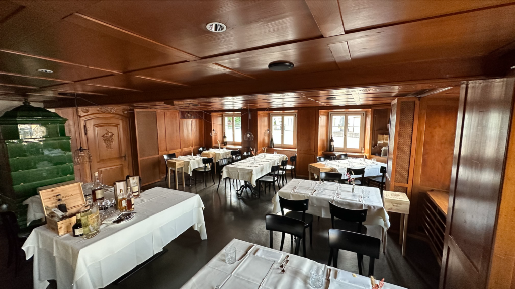
THIS CONTENT IS AUTOMATICALLY TRANSLATED BY GOOGLE TRANSLATE. The Scala is a lively meeting place for artists and cultural workers from all over Switzerland and beyond. Since 2003, the Scala has had its home in the venerable “Ochsen”. The inn was built in 1583 and can therefore look back on 440 years of history. In addition to the actual event location, the project includes a bar and a restaurant.
The historical building structure, the attached restaurant, high visitor numbers and more require optimal ventilation of the rooms. Although the Scala had a ventilation system, the control system was defective.
The aim of the retrofit project was to preserve the historic building and equip it with suitable, efficient and, above all, intelligent ventilation control.
Solution
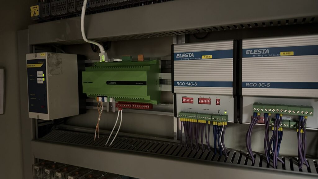
THIS CONTENT IS AUTOMATICALLY TRANSLATED BY GOOGLE TRANSLATE. In this retrofit project, a total of two mini servers take over the intelligent control of the ventilation and heating system (the separation was due to the spatial distance between the heating and ventilation system). The complete automation of the existing system could be achieved with just a few components: The CO2 measurement is carried out via room climate sensors, the actual control is carried out by various Belimo components. The existing frequency converters were integrated into the ventilation control and controlled with 0-10V.
The Scala's event calendar has been linked to Loxone so that the ventilation and heating can automatically carry out preparatory work before an event. The hall is therefore ready for its guests at the right time with the right room climate.
1. Air volume control:
The air volume control is implemented via fan optimizer programming (bad point control). This means that the air volume of the fans, supply air and exhaust air is regulated as required depending on the volume flow controllers or their pumped air volume.
The differential pressure sensors in the 3 ventilation devices can be seen as the actual value. The sum of the active air volumes via the volume flow controller is used as the setpoint. The air volume is calculated in the software.
An exception is the kitchen exhaust air. It was important to ensure that the amount of air in the exhaust air was controlled depending on the volume flow controller in the supply air so that there was always a negative pressure in the kitchen. Here too, the air volume of the volume flow controller in the supply air is used as a setpoint, with a defined shortfall.
Kitchen
The existing rotary switch (0/Auto/S1/S2) in the kitchen was retained. Depending on the position, this regulates the kitchen ventilation. The air volume of the volume flow controller can be individually adjusted for levels 1 and 2.
The fan is controlled according to the flap position.
bistro
The room climate sensor currently has no regulating effect. It currently only provides values. A later implementation for regulation is possible at any time.
room
The room climate sensor records temperature, humidity and air quality. If the air quality is poor, the ventilation is switched on (if it is not already running). The Belimo volume flow controllers are regulated to a setpoint (adjustable). The worse the air quality, the more the volume flow controllers are opened. In addition, the air volume can be increased or decreased manually.
bar
Analogue hall.
Duct exhaust air sensors
Belimo sensors are placed in the exhaust air ducts of the dining room, bistro, bar and in the shared exhaust air of the gallery and hall and measure temperature, humidity and air quality. The air quality of the exhaust air has the same effect as the air quality in the rooms. For example, if the bar's exhaust air duct sensor measures poorer air quality than the bar's room climate sensor, it takes control of the corresponding controller.
Air heater
The air heater pump and air heater valve are located in the attic. There is no bypass. If there is a need for thermal energy, not only is the air heater pump and the air heater valve activated, but a demand message is also sent to the mini server, which switches on the main pump.
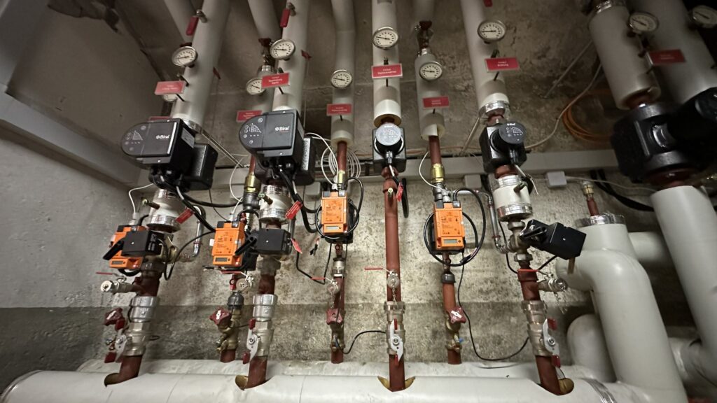
2nd circuit network system (KVS)
Energy recovery (heating or cooling) is carried out by the KVS. The temperature sensor serves as frost protection. If it is colder than 2°C (adjustable), the bypass valve is constantly opened to ensure frost protection in the exhaust air.
The pressure switch is used to monitor the system. The pump is controlled via a 0-10V signal, depending on how much volume is available from the two heat recovery valves.
2.1 Icing protection regulation
The dew point determined is the setpoint for the sensor at the outlet of the KVS register in the supply air. As long as the dew point, which is determined in the respective exhaust air via the humidity and temperature, is above 0°C, the exhaust air register flow temperature is kept above 0°C with the help of the bypass valve. If the determined dew point temperature falls below 0°C, the outlet temperature is also maintained at exactly this value by constantly opening the bypass valve.
2.2 Delta-T control
The Belimo Energy Valve maintains a 2-3 K lower temperature in the exhaust air at the respective outlet of the KVS register than in the exhaust air. This ensures optimal heat transfer. The circulation pump is operated at constant pressure. The start sequence in the ERG case is selected depending on the temperature range in the two exhaust air devices.
3. Temperature control
Since these are event rooms and are also equipped with static heating (radiators), a constant supply air temperature control is recommended. This is also ideal for the kitchen.
To provide the best experiences, we use technologies like cookies to store and/or access device information. Consenting to these technologies will allow us to process data such as browsing behavior or unique IDs on this site. Not consenting or withdrawing consent, may adversely affect certain features and functions.
Functional
Always active
The technical storage or access is strictly necessary for the legitimate purpose of enabling the use of a specific service explicitly requested by the subscriber or user, or for the sole purpose of carrying out the transmission of a communication over an electronic communications network.
Preferences
The technical storage or access is necessary for the legitimate purpose of storing preferences that are not requested by the subscriber or user.
Statistics
The technical storage or access that is used exclusively for statistical purposes.The technical storage or access that is used exclusively for anonymous statistical purposes. Without a subpoena, voluntary compliance on the part of your Internet Service Provider, or additional records from a third party, information stored or retrieved for this purpose alone cannot usually be used to identify you.
Marketing
The technical storage or access is required to create user profiles to send advertising, or to track the user on a website or across several websites for similar marketing purposes.
Get your copy of our New Partner Guide and discover how to become a Loxone Partner and all the benefits that come with it!
Interested in Becoming a Loxone Partner?
Connect with a Loxone Pro to answer whatever questions you have about the company, partner program, technology and more.
Download your Intro to Smart Homes now
Discover the world of intelligent automation with our expert-written Intro to Smart homes. Gain valuable insights, industry trends, and deep technical knowledge to optimize your automation projects. Whether you’re a professional or an enthusiast, our Intro to Smart homes provides you with the expertise you need.
Download your Smart Home Checklist now
The Loxone Smart Home Checklist is a comprehensive guide designed to help you plan and implement Loxone automation solutions in your future home. To help you think about every step in the construction phase of your smart home, here is a short checklist with the most important areas of application.
The definitive Loxone guide – everything you need to know.
Loxone Automation – Intelligent control for homes and buildings. Seamlessly manage lighting, climate, security, and energy with the Loxone Miniserver. Easy setup, intelligent automation, and third-party integration for a smarter, more efficient space.
Download your Hospitality Compendium now
Discover how Loxone is transforming the hospitality industry with intelligent automation. The Hospitality Compendium offers expert knowledge, best practices and practical applications – all in one convenient digital hub. Browse, download, and improve your guest experience today!
Your e-book for smart lighting
A must-read for smart home enthusiasts and professionals. Discover how smart lighting increases comfort, efficiency and automation. This e-book contains key concepts, design tips, and practical applications to help you optimize your lighting.
Your Free Source of Inspiration
Discover expert insights on the future of smart living. Your essential guide to smart home automation. Discover the latest trends, products and solutions for homeowners, architects and business owners who want to integrate intelligent control systems.
Your Free Source of Inspiration
Your first port of call for inspiration on commercial building automation. Find out about the latest trends, products and innovations – for professionals, architects and business owners who want to integrate intelligent control systems.
Subscribe to our newsletters…
Sign up to our newsletters and be the first to receive news, exclusive offers and more:
Get information about new products and software,
Tips for energy saving and more
Ideas & inspiration for your smart home or commercial project
Follow us on social media to stay up-to-date with the latest news from Loxone.