Instructions to get your RGBW 24V Dimmer DMX installed and configured.
ABOUT
The RGBW Dimmer DMX is designed to be placed in the central location with all the other Loxone equipment as the dimmer is designed to fit on DIN rails. This dimmer has 4 channels so RGBW LED tape can now be easily dimmed. This page will show you how to wire up the dimmer and also how to add it in to Loxone Config.
TECHNICAL DATA
- Power requirements: 24VDC
- Rating per channel: 50W (equivalent to 2.1A)
- Outputs can be bridged
- Power consumption: < 150mW
- Dimming: 1…100% @ 123Hz
- Operating temperature: 0 to 55°C
- Max. cable length from dimmer to LED strip: 30m
LED STATES
The Status LEDs flash orange at first. After the Dimmer has been learnt in to the DMX Extension the LEDs blink green to confirm this was successful and then both the LEDs are off permanently.
INSTALLATION
The diagram below shows how you wire up the RGBW Dimmer DMX. It is the same DMX bus topology as with the PWM Dimmers, but now the dimmers are all in the same location as the DMX Extension so you don’t have to run the DMX bus round the whole installation.
You can, of course, have multiple locations for the RGBW Dimmer DMX’s, the maximum length of the bus is 500m. The maximum distance from the dimmer and the tape is 30m.

If you have selected PWM in the device properties using the ‘Dimmer individual channels’, then the channel assignments are as follows:
Red -> Dimmer 1
Green -> Dimmer 2
Blue -> Dimmer 3
White -> Dimmer 4
SETUP IN LOXONE CONFIG
Once you have wired up the RGBW Dimmer’s to the DMX Extension then you can now set them up in Loxone Config so you can control your LED strips from the app or web interface. Follow these steps to find out how:
STEP 1: DMX SEARCH
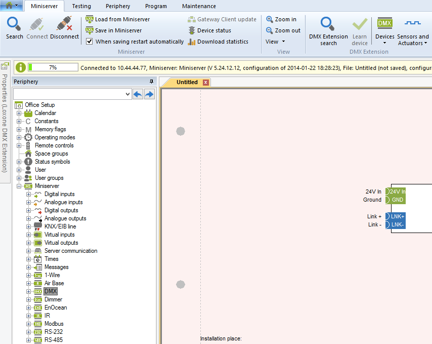
Now all your dimmers are connected you can search for them using the DMX Extension. Click on the DMX Extension in the periphery tree and then in the Context menu in the top bar click on DMX Extension Search.
STEP 2: ADD THE RGBW DIMMER
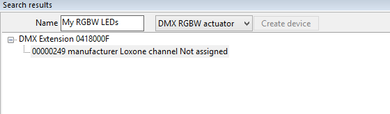
You will see all the RGBW Dimmer’s listed in the DMX search window now. To add one to the program click on the respective dimmer, enter a name, select the type and then click Create device.
The type can either be DMX RGBW actuator (for controlling RGBW LED strip) or DMX 4 actuators (you can control 4 outputs separately for example 4 single colour white strips).
STEP 3: SAVE IN MINISERVER
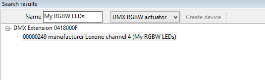
Now save the program in the Miniserver and you will see when you do the DMX Extension search again that the channel has now been learnt in.
STEP 4: USE THE OUTPUTS
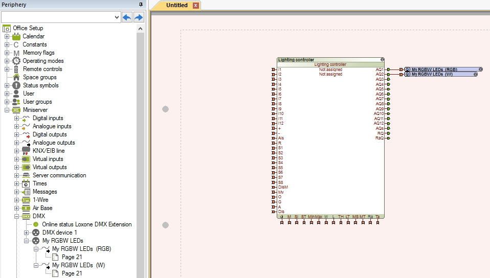
The dimmer is now listed in the periphery tree window so you can drag and drop the outputs into pages to use in your program.
DIAGNOSTIC CHECKLIST
For RGBW 24V dimmer DMX which are not found in the search or do not communicate correctly.
General guidelines for diagnostic
Work on the wiring and termination of inputs/outputs, link connections, or replacing individual devices. This must ONLY be carried out with the power off!
Before restarting, you should check again if all connectors are plugged in, then switch on the power supply again.
1.
Make sure that the dimmer is has the correct serial number included in the configuration and is saved in the Miniserver. Connect to your Miniserver and load the PLC program from the Miniserver. Now select the respective dimmer in the peripheral area. The selected RGBW dimmer now flashes red green alternately.
2.
Now check whether the two terminals are connected correctly at the bottom or the wires have been clamped on the insulation (this will interfere with communications). A wire may be broken or the insulation pinched.
In addition, check whether the last extension on the DMX bus is terminated with a 120 Ohm resistor.
If there are several power supplies, make sure that GND of all power supplies are connected to each other. If this connection is not present, there may be communication errors on the DMX interface due to potential differences between the power supply units, this is sometimes also referred to as floating voltage.
3.
Now take a rsitstance meter (eg multimeter) to measure the resistance between the two poles of the DMX interface and the DMX interface to GND.
(Measure directly on the pins of the RGBW 24V dimmer DMX not on the Phoenix connector as this can skew results)
Here is a table of typical resistance values:
| Connection | Resistance Value |
| DMX-DMX | 430 kOhms |
| DMX + – GND | 6 MOhms |
| DMX – – GND | 6 MOhms |
4.
After checking that all plugs have been plugged in correctly, you can reactivate the power supply. If the problem still persists, please contact support.