The Loxone Intercom is a compact video door station featuring a glass finish, illuminated bell button and proximity sensor. It is available in two colour options.
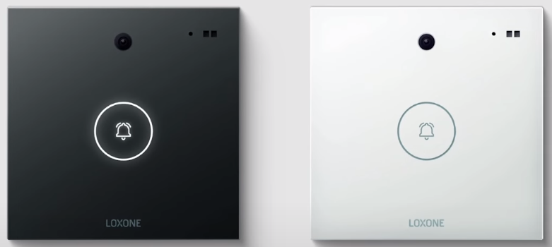
The microphone is embedded into the front panel, the concealed speakers are located on unit's left side.
The device is connected to the network and powered via PoE (Power over Ethernet).
The integrated Tree interface makes it possible to connect an NFC Code Touch as part of an access solution.
The installation is surface-mounted in a flat frame made of aluminium, which is available as an accessory in a single or double version.
The Intercom is compatible with every type of the Loxone Miniserver.
Table of Contents
- Mounting
- Commissioning
- Programming
- Connection to other devices
- Proximity sensor
- Bell Button Sensitivity
- Speaker Volume
- Intercom Update Level – Registering for Test Firmware
- Maintenance and cleaning
- SD Card
- LED States and Diagnosis
- Factory Reset, Settings and Updates
- Inputs, Outputs, Properties
- Safety Instructions
- Documents
Mounting↑
Depending on the application, the mounting height should be selected in such a way that adults are well captured by the camera, while children can still press the call button. We recommend a mounting height to the top edge of the device of 1600mm.
A junction box behind the mounting frame is not required, but highly recommended for tucking away connecting wires or a spare loop.
Please note the non-standard box spacing of 98mm when using the double or triple mounting frame.
Care must be taken not to cover the speaker openings on the left side of the frame.
The anthracite version of the intercom must not be mounted in places exposed to direct sunlight, as overheating may occur.
Install the Mounting Bracket by affixing it onto a level surface. Make sure that the TOP marking of the frame is at the top:

Standard solid core network cable, CAT5 and up, can be used to connect to the local network. Remove about 5 cm of the cable jacket and prepare the orange/white and green/white cores for connection. The other two twisted pairs are not needed and must be made safe.
Strip the cores, then insert them into the matching coloured orange/white and green/white push-in terminals:

 | Do not connect any power supply other than PoE to the device! |
| Power Supply: Power over Ethernet (PoE), typ. 48VDC IEEE 802.3af Mode A, power class 0 |
The core assignment in the colour shown corresponds to T568B termination. In a network wired according to T568A, the green and orange pairs are swapped.
As the Intercom is capable of Auto MDI-X, operation is ensured in either assignment.
For a compliant connection according to T568A, the orange and green terminal pairs can be interchanged, but this is not technically necessary.
Optionally, an NFC Code Touch as access control or other devices can be connected to the designated terminals (24V output and Tree interface).
A self-adhesive cover is included in the delivery to protect against water. It must be attached above the terminals once connected.
Two markings at the top edge of the housing help with positioning:

Finally, mount the device to the Mounting Bracket by first inserting the top and then snapping the bottom into place.
To detach the device from the Mounting Bracket, a suction cup can be used to pull the device off the bracket.
After connecting the intercom, connect the other end of the network cable to the PoE injector, which is available as an accessory. The second port of the PoE injector is connected to the network.
Alternatively, use the port of a PoE Mode A capable switch instead of the PoE injector.
Only PoE Mode A uses 4 common lines for power supply and data transmission. At the RJ45 socket the power is delivered via pins 1/2 and 3/6. Make sure that the used PoE supply works this way.
The Intercom starts as soon as the power supply is switched on, and is ready for operation after about 1 minute.
Wait until the Intercom is fully operational.
The device can now be commissioned as described in the following instructions.
Commissioning↑
During initial setup, the Intercom is ready for pairing with the Miniserver after start-up. This is indicated by the status LED flashing red/green/orange.
Open Loxone Config and connect to the Miniserver. In the periphery tree, first select Network Periphery, then click on Network Device Search in the menu bar
After a few moments, the Intercom should be listed among the network devices in the search window:

If you select an Intercom here, it will identify by quickly flashing the bell button red/green. This also allows multiple devices to be assigned and named.
Highlight the Intercom and click on Configure Device to assign a static IP address to the Intercom.
Then assign a name, room and installation location for the selected Intercom and add it to the program using the Pair Device button or the + symbol and save the program to the Miniserver.
Afterwards, the Intercom is ready for use in configuration in the Loxone Config periphery tree.
The ports and domains used are listed in detail in the document of the same name at the bottom of this page.
Programming↑
The device is programmed and set up using the Intercom function block in Loxone Config.
Drag the Intercom from the periphery tree to the programming page to create the function block.
Connection to other devices↑
The Loxone Intercom also provides a Tree interface and a 24V output to power additional devices. For example, an NFC Code Touch can be connected to the Intercom as part of an access control solution.
The new version of the NFC Code Touch (100480, 100481, 100482, 100483) can be mounted together with the Intercom in a double bracket, sold separately:

When mounting in the double bracket, vertical positioning of the bracket is preferred and the intercom must be inserted at the top as shown.
When using the double bracket horizontally, the intercom can be inserted on the left, but audio quality is impaired in this case as there are no openings for the speakers in the bracket at this position.
| The devices connected to the 24V power output and the Tree interface of the Intercom must remain independent of the rest of the installation. No connection to other Tree branches, power supplies or devices may be established, not even via a common GND. |
To pair connected Tree devices select the Intercom's Tree interface in the periphery tree in Loxone Config, and start the Tree device search.
Proximity sensor↑
The infrared proximity sensor on the glass front detects objects in front of the Intercom.
When an object is detected, the bell button illumination of the Intercom is activated.
Furthermore, the motion input is activated, which can be used freely in programming.
Due to the technology used, not only people are detected, but also other objects in motion. In addition, the range of the proximity sensor is shorter in daylight than in darkness.
For this reason, and because of the narrow angle of detection, it is not a fully-fledged replacement for a motion or presence sensor.
If there is an object in the border area of the sensor range, for example an opposite wall, it can happen that this is only detected temporarily. This also activates the illumination and the motion input.
To prevent this, you can use the webservice command <IP-Intercom>/dev/tof/set/rangelimit/x to reduce the range of the proximity sensor and <IP-Intercom>/dev/tof/get/rangelimit/ to query the set limit.
In the following example the range is limited to 100cm: <IP-Intercom>/dev/tof/set/rangelimit/100
Bell Button Sensitivity↑
If the bell button of the Intercom is not responding as expected, you can adjust its sensitivity level.
Check Current Sensitivity Value
First, obtain the current sensitivity setting using the command below:
http://<ip-intercom>/dev/touch/get/TOUCH_THRESHOLD
The default sensitivity value is 100.
Adjust Sensitivity Value
To change the sensitivity, use the following command:
http://<ip-intercom>/dev/touch/set/TOUCH_THRESHOLD/<v>
Increasing the value decreases sensitivity, making the button less responsive to touch.
Decreasing the value increases sensitivity, making the button more responsive.
It is recommended to adjust this setting only slightly from the default value of 100 to achieve the desired responsiveness.
Speaker Volume↑
If the Intercom is too quiet or too loud for its surroundings — for example on a busy road — you can adjust the volume of its speaker.
Check Current Volume
First, obtain the current volume setting using the command below:
http://<ip-intercom>/dev/audio/amp/get/volume
The default volume value is 10 dB.
Adjust Volume
To change the volume, use the following command:
http://<ip-intercom>/dev/audio/amp/set/volume/<x>
Replace <x> with a value between 0 dB and 24 dB. Higher values increase the volume, lower values decrease it.
In the following example the volume is set to 15 dB: http://<ip-intercom>/dev/audio/amp/set/volume/15
Intercom Update Level – Registering for Test Firmware↑
In some situations, it may be required to install a test version of the Intercom firmware to confirm whether a particular issue has been resolved or for additional troubleshooting. To enable the Intercom to install this test version, follow these steps:
Register for test firmware
Execute the following command to register the Intercom for the Test firmware:
http://<ip-intercom>/dev/cfg/updatelevel/alpha
The Intercom is now registered to receive test firmware updates.
Install test firmware
After the registration for the test firmware version, return to the Intercom’s web interface. A pop-up notification will appear, prompting you to install the new test firmware version.
Return to release version
Once the test firmware has been installed, it is important to re-register the Intercom for the official release version to avoid automatic updates to subsequent test versions. Use the following command to return to the release version:
http://<ip-intercom>/dev/cfg/updatelevel/release
Maintenance and cleaning↑
Use a damp, soft cloth to clean the front panel of the device.
Avoid getting any dirt into the openings for the microphone and speaker.
SD Card↑
The Micro SD card, located at the bottom edge of the back of the Loxone Intercom, contains the operating system and settings. The SD card slot is protected by a sticker.

The SD card can be removed as follows:
Pull off the sticker and gently press the visible edge of the SD card with your fingernail or a small flat screwdriver.
This will release and partially eject the card so it can be removed.
If the SD card fails to latch when inserting it, it needs to be fully removed to reactivate the latching mechanism.
After re-inserting the card, the slot must again be sealed with a sticker of the same or a similar type in order to protect the internal electronics from moisture.
LED States and Diagnosis↑
The illuminated bell button of the Intercom also serves as a status indicator. Typical and possible LED States are listed below:
Boot Phase
The Intercom starts as soon as the power supply is switched on. This is indicated by the following sequence:
Red, Yellow, Orange in succession: Booting started, please wait.
Constant Yellow: Intercom is booting, please wait.
Constant Orange: Intercom is trying to connect to the Miniserver, please wait.
Red/Green/Orange alternating: Ready for pairing with the Miniserver.
LED States
Off or white: Normal operation, LED can be activated automatically or manually.
Rapid red/green flashing: Device is selected in Loxone Config and is identifying.
LED states indicating errors during operation or while booting
Permanent red: SD card is not inserted or cannot be detected.
Rapid red/green flashing: Intercom operating system cannot be found on SD Card.
LED off, not flashing: No power, please check wiring, connections, POE injector and power supply, or POE switch.
Voice Message
If the connection to the Miniserver is lost and someone rings the Intercom, the voice message “Error” is played on the device.
Factory Reset, Settings and Updates↑
If the Intercom was previously paired with a Miniserver and is now to be used in another installation, the pairing must first be released.
Connect to the Miniserver and delete the Intercom from the programming. Then save the program into the Miniserver.
If the Intercom pairing was not released, it will try to reach the previously paired Miniserver after starting.
If it cannot connect to the Miniserver, the Intercom will go into pairing mode 15 seconds after booting, and indicate this by the corresponding LED status.
The Intercom can then be paired with a new Miniserver.
The Intercom will continue to try to reach the Miniserver it was previously paired to. If the connection can be re-established, the Intercom will end pairing mode.
If no connection or pairing is established, the Intercom will automatically end pairing mode after 120 minutes.
Once the Intercom is paired with a new Miniserver, it will no longer attempt to contact the previous Miniserver.
The Intercom can be reset to Factory Settings by formatting an SD card for the Intercom in Loxone Config and then inserting it into the device.
The Web Interface of the Intercom allows network configuration, status display and diagnostic options. You can access it via the IP address or the hostname of the Intercom. When searching for Intercoms in Loxone Config, the search result includes the IP address or hostname of the Intercom.
If the Intercom is not yet paired with a Miniserver, the login credentials for the web interface are admin/admin.
Once the Intercom is paired, the login credentials of a user of the user group Full Access (Administrators) of the paired Miniserver are required.
If a firmware update is available, a notification will be displayed in the System Status in the App and in Loxone Config, which allows you to start the update directly.
Alternatively, the Intercom can be updated manually in Loxone Config. To do so, select the Intercom in the periphery tree and click on Update Intercom Firmware in the menu bar. The update can also be started from the Intercom web interface.
If there is no DHCP server in your network, or if the Intercom is connected directly to a PC, link-local addressing via Zeroconf is supported. If both Intercom and computer are set to DHCP, they will adopt a 169.254.x.x link-local address.
This way a direct connection to the Intercom is possible even without a network. Although this is not suitable for normal operation, it allows you to access the Intercom's web interface and settings.
Diagnostic Inputs↑
| Summary | Description | Unit | Value Range |
|---|---|---|---|
| Sabotage | Input is active under normal conditions and signals a possible sabotage attempt, e.g. if the Intercom is disconnected or no longer reachable. Function: If the Miniserver loses the connection to the Intercom, the Miniserver will try for 10 seconds to re-establish the connection. If the connection cannot be re-established, but the Intercom is reachable via a ping (e.g. when the Intercom is restarting), the Miniserver will continue to try for 60 seconds. After this time the device is set offline, sabotage is reported and the input is deactivated. | - | 0/1 |
| Online Status Intercom | Indicates whether the device can be reached by the Miniserver. Diagnostics for Air devices Diagnostics for Tree devices Diagnostics for Extensions | Digital | 0/1 |
| Temperature Shutdown | Input is active, when the outputs of the device have been switched off due to high device temperature. Possible reasons: Ambient temperature too high, outputs overloaded. | Digital | 0/1 |
Sensors↑
| Summary | Description | Value Range |
|---|---|---|
| Bell Button | Input is active when the bell button on the Intercom is pressed. | 0/1 |
| Motion | Input is active when an object is detected by the proximity sensor. | 0/1 |
Actuators↑
| Summary | Description |
|---|---|
| API Connector | Intelligent API based connector. API Commands |
Properties↑
| Summary | Description | Unit | Value Range | Default Value |
|---|---|---|---|---|
| Serial Number | Specifies the serial number of the device. | - | - | - |
| Monitor Online Status | If checked, you will be notified via System Status or the Mailer if the device is no longer available or goes offline. | - | - | - |
| Monitor Tamper Status | If checked, you will be notified of possible sabotage attempts via System Status or Cloud Mailer. | - | - | - |
| Miniserver | Miniserver this device is paired to | - | - | - |
| Network Address | IP address or hostname of the device on the local network | - | - | - |
| Overrun time motion | The 'Motion (Mo)' input remains active for the specified overrun time after the last motion was detected. The longer the set overrun time, the fewer packets have to be sent on the network. Value = 0 deactivates motion. | s | 0...900 | - |
| Video Framerate (Internal) | Video framerate when connected locally. | - | - | - |
| Video Resolution (Internal) | Video resolution when connected locally. | - | - | - |
| Video Framerate (External) | Video framerate when connected remotely. If your remote connection is slow, it is recommended to use a lower framerate. | - | - | - |
| Video Resolution (External) | Video resolution when connected remotely. If your remote connection is slow, it is recommended to use a lower resolution. | - | - | - |
| Maximum number of saved photos | Maximum number of photos saved on the Intercom. To delete already saved photos, set this value to 0. | - | 0...100 | 100 |
| Device Configuration | Edit device settings. A connection to the Miniserver is required. | - | - | - |
Safety Instructions↑
Installation must be carried out by a qualified electrician in accordance with the applicable regulations.
The speaker of this device is magnetic. To avoid damaging it, make sure that no metal parts, chips or dirt get near the speaker.
Documents↑
Datasheet Mounting Bracket Single
Datasheet Mounting Bracket Double