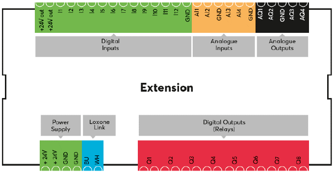
The Extension features 8 potential free relay outputs, 12 digital inputs, 4 analogue 0-10V inputs and 4 analogue 0-10V outputs.
The digital inputs can also be used as frequency counters, to connect for example S0 meters or wind sensors that transmit pulses.
The analogue inputs can also be used as digital inputs.
Table of Contents
Commissioning↑
The Extension is installed on a DIN rail in a suitable enclosure.
Connect the power supply and Link communication to the Miniserver.
Connect the loads to the relay terminals. You will find various connection examples below.
 | Many electronic loads such as ballasts, power supplies, LED drivers and high voltage LED lamps can draw high inrush currents of over 20A. Use inrush current limiters or a coupling relay with the necessary current rating for such cases. |
If the devices are connected to different power supplies, it is essential that the GNDs are interconnected.
The Extension starts after switching on the power supply, and the status LED will flash orange after a short time when the connection to the Miniserver is established.
Then follow the pairing procedure on the Link Interface.
Wiring examples↑
Connecting coupling relays for higher load switching
Connect sensors with open collector outputs
Connecting a 230V motion sensor to a digital input
Connecting 0-10V temperature sensors
Connecting analogue actuators (0-10V)
Sensors↑
| Summary | Unit | Value Range |
|---|---|---|
| Input 1 | Digital | 0/1 |
| Input 2 | Digital | 0/1 |
| Input 3 | Digital | 0/1 |
| Input 4 | Digital | 0/1 |
| Input 5 | Digital | 0/1 |
| Input 6 | Digital | 0/1 |
| Input 7 | Digital | 0/1 |
| Input 8 | Digital | 0/1 |
| Input 9 | Digital | 0/1 |
| Input 10 | Digital | 0/1 |
| Input 11 | Digital | 0/1 |
| Input 12 | Digital | 0/1 |
| Voltage 1 | - | ∞ |
| Voltage 2 | - | ∞ |
| Voltage 3 | - | ∞ |
| Voltage 4 | - | ∞ |
Actuators↑
| Summary | Unit | Value Range |
|---|---|---|
| Actuator (Relay) 1 | Digital | 0/1 |
| Actuator (Relay) 2 | Digital | 0/1 |
| Actuator (Relay) 3 | Digital | 0/1 |
| Actuator (Relay) 4 | Digital | 0/1 |
| Actuator (Relay) 5 | Digital | 0/1 |
| Actuator (Relay) 6 | Digital | 0/1 |
| Actuator (Relay) 7 | Digital | 0/1 |
| Actuator (Relay) 8 | Digital | 0/1 |
| Voltage 1 | - | ∞ |
| Voltage 2 | - | ∞ |
| Voltage 3 | - | ∞ |
| Voltage 4 | - | ∞ |
Diagnostic Inputs↑
| Summary | Description | Unit | Value Range |
|---|---|---|---|
| Online Status Extension | Indicates whether the device can be reached by the Miniserver. Diagnostics for Air devices Diagnostics for Tree devices Diagnostics for Extensions | Digital | 0/1 |
| System temperature | Provides the internal device temperature. This is often the temperature of the CPU or another location in the device. | ° | ∞ |
| Temperature Shutdown | Input is active, when the outputs of the device have been switched off due to high device temperature. Possible reasons: Ambient temperature too high, outputs overloaded. | Digital | 0/1 |
Properties↑
| Summary | Description | Default Value |
|---|---|---|
| Serial Number | Specifies the serial number of the device. Enter 'Auto' to automatically pair an Extension with unknown serial number. This can only be used if there is only one Extension of the same type on a standalone Miniserver (not in a Client-Gateway setup). Save in the Miniserver to pair the Extension. Afterwards the program must be loaded from the Miniserver to transfer the actual serial number of the Extension into the program. | - |
| Monitor Online Status | If checked, you will be notified via System Status or the Mailer if the device is no longer available or goes offline. | - |
Safety Instructions↑
Installation must be carried out by a qualified electrician in accordance with the applicable regulations.
This device must be mounted on a DIN rail in an electrical distribution enclosure to ensure protection against contact, water and dust.