MODBUS BASICS
Modbus is a serial communications protocol that is based on the RS-485 standard. Modbus uses the master-slave arrangement where one device initiates all the communication activity.
In a Loxone system the Modbus Extension is the master device and it can be connected with up to 32 slave devices on a 2-wire bus (exactly how RS-485 is wired with a twisted pair connecting A and B on each device).
Modbus is chiefly used in industrial control applications. A wide variety of transmitters, frequency converters, actuators, room controllers etc are already equipped with a Modbus interface.
SETTINGS
If you click on the Modbus Extension in the periphery tree window you will see the Properties of the extension displayed in the properties window to the far left of the screen. Here you must set the baud rate, stop bits and parity. These settings are product specific so please find the details from the manufacturer’s data sheet for the Modbus device you are using.
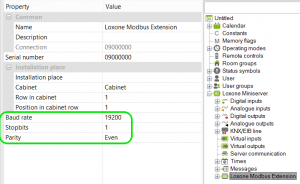
![]() You can control up to 32 Modbus devices off one Modbus extension but all devices must have the same baud rate, stop bits, and parity settings.
You can control up to 32 Modbus devices off one Modbus extension but all devices must have the same baud rate, stop bits, and parity settings.
ADD IN A MODBUS DEVICE
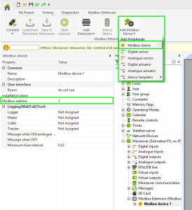
Click again on the Modbus Extension in the periphery tree window and you will see in the top ribbon a button called ‘Sensors and Actuators’. In this menu select ‘Modbus device’, or you can choose from a list of pre-defined devices.
SENSORS AND ACTUATORS
To create a sensor or actuator, select the Modbus device in the peripheral tree. In the top ribbon the button called ‘Sensors and Actuators’ will now show both analogue and digital sensors and actuators. Select the desired type and it is added in underneath the selected Modbus device.
SENSORS
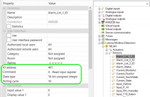
In the Properties window of the sensor, you need to enter the IO address (register address), select the type of command, choose the data type (for analogue sensors only) and finally enter the a polling cycle (time interval in which the sensor value is updated).
The information relating to the IO address and the type of command and data will be provided by the manufacturer as it is product specific.
![]() The data the Modbus Extension receives is forwarded via the Loxone Link to the Miniserver. Please note therefore that too frequent polling cycles may tax the bus, so it is advisable to set sensible intervals (i.e. Not every change for a temperature sensor).
The data the Modbus Extension receives is forwarded via the Loxone Link to the Miniserver. Please note therefore that too frequent polling cycles may tax the bus, so it is advisable to set sensible intervals (i.e. Not every change for a temperature sensor).
ACTUATORS
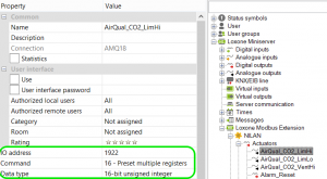
Here you need to enter the IO address, choose the command type and the data type (analogue actuators only).
Again the information relating to the IO address and the type of command and data will be provided by the manufacturer as it is product specific.
SAVE AS A TEMPLATE
After adding all the required sensors and actuators to your Modbus device you can save it is a template so you can use it again.
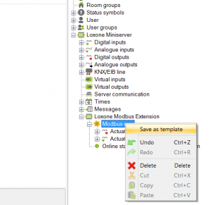
Click on the Modbus Extension in the periphery tree window to highlight it, and then right click to bring up a little menu box. Choose the option ‘Save as template’.
A Save As window will pop up and you can then replace the xxx in the file name with a name for the Modbus device.
The file path you need to save this file in is:
C:\ProgramData\Loxone\LoxoneConfig version number\ENG\Comm
If you cannot see the ProgramData folder you need to enable hidden folders/files in Windows explorer.
Always make sure the file name begins with MB_ and then when your file is named click Save. You will need to then restart Loxone Config and you will see the device listed as one of the pre-defined devices.