The Loxone Valve Actuator Tree is a motorized valve actuator for heating systems. By using common adapter rings, it can be mounted on a wide range of valves, which are typically used for radiant floor heating and radiators.
Datasheet Valve Actuator Tree Gen.1
Table of Contents
- Mounting
- Commissioning
- LED states
- Device test and calibration run
- Inputs, Outputs, Properties
- Safety Instructions
- Documents
Mounting↑
In delivery state, the valve is fully open. The Valve Actuator Tree performs a calibration run only after powering on, so it must be installed before initial start-up. Before mounting, make sure that the valve pin is movable and not rusted.
Then snap the actuator onto the adapter ring. Do not apply excessive force. Make sure that the actuator is correctly positioned on the valve. Only use valve adapters suitable for the valve.
 | Ensure that the correct adapter is used for the specific valve type. Using an unsuitable adapter may lead to issues, such as "valve stuck" or "no valve detected" messages. The adapter also positions the valve stem correctly. |
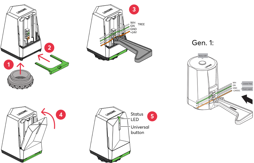
We recommend using the Loxone Tree Cable or Panel Wire, both 0.8mm Ø, to wire the actuators.
Use the IDC tool to push the orange/white wire pair to connect the power supply and the green/white wire pair to connect the Tree data lines.
We recommend a short service loop between the individual actuators and securing the cable near the first actuator for strain relief.
The wires are pressed into the terminals of the actuators using the IDC Tool (100226) supplied with the Miniserver or Tree Extension.
| Make sure that no water can drip onto the actuator. Although the actuator can be mounted in any position, it is recommended to install the actuator above the valve to prevent water dripping onto the actuator in case of a leaking valve or condensation. |
| When installing the Valve Actuator, ensure that the opening for the green mounting clip does not face downward. Installing the Valve Actuator in this position may cause the clip to loosen or fall out, potentially leading to malfunction or improper operation of the valve. |
 | If a large number of valve actuators share one electrical line with a small wire cross-section, significant voltage drop may occur. In such a case, it is recommended to use a larger wire cross-section for the 24V supply line and to switch to a smaller cross-section just before connecting the actuators. |
A separate circuit is recommended for the power supply of the actuators. Note the inrush current of 50mA at 24VDC. In order to avoid load peaks at the moment of switch-on, a maximum of 5 actuators will start moving simultaneously.
Commissioning↑
Then follow the pairing procedure on the Tree Interface.
After powering on, the calibration run starts. The Valve Actuator determines the valve travel and registers the 0% and 100% positions.
If necessary, a Recalibration can be triggered via Loxone Config.
By default, the actuator then moves to the 0% position (valve closed). Programming must be created to open the valve again.
LED states↑
Please note that the status LEDs do not light up while the actuator is moving.
| LED state | Description |
|---|---|
| No communication to Miniserver possible. Please check the wiring. |
| Tree Device was detected on Tree bus, but is not paired with Miniserver. |
| 3 short flashes Communication OK, device paired. |
| Device is in pairing mode, ready for pairing. |
| Device was selected in Loxone Config and is identifying. |
| Online, valve open more than 90%. |
| Online, valve open between 10% - 90%. |
| Online, valve less than 10% open. |
| The error "valve stuck" or "no valve detected" is present. Please check the valve pin, it should be easily movable. |


Device test and calibration run↑
The actuator can be fully opened or closed for test purposes.
In addition, the actuator can be recalibrated.
Right-click on the actuator in the Periphery tree and select an option:
Device test on: Fully open actuator/valve
Device test off: Fully close actuator/valve
Recalibrate device: Perform calibration run.
Sensors↑
| Summary | Description | Unit | Value Range |
|---|---|---|---|
| No valve detected | No valve was detected. Input deactivated in Loxone Config. | - | 0/1 |
| Valve is stuck | Indicates a stuck valve. Input deactivated in Loxone Config. | - | 0/1 |
| Input 1 | Digital | 0/1 |
Actuators↑
| Summary | Description | Unit | Value Range |
|---|---|---|---|
| Valve Actuator | Valve Actuator. | - | - |
| Valve Actuator Tree | % | ∞ |
Diagnostic Inputs↑
| Summary | Description | Unit | Value Range |
|---|---|---|---|
| Online Status Valve Actuator Tree | Indicates whether the device can be reached by the Miniserver. Diagnostics for Air devices Diagnostics for Tree devices Diagnostics for Extensions | Digital | 0/1 |
| No Valve Detected | Valve Actuator Tree | Digital | 0/1 |
| Valve is stuck | Valve Actuator Tree | Digital | 0/1 |
Properties↑
| Summary | Description | Default Value |
|---|---|---|
| Monitor Online Status | If checked, you will be notified via System Status or the Mailer if the device is no longer available or goes offline. | - |
| Serial Number | Specifies the serial number of the device. Enter 'Auto' to automatically pair a Tree device with unknown serial number. This can only be used if there is only one Tree device of the same type on a standalone Miniserver (not in a Client-Gateway setup). Save in the Miniserver to pair the Tree device. Afterwards the program must be loaded from the Miniserver to transfer the actual serial number of the Tree device into the program. | - |
| Switch off status LEDs | If checked, the status LEDs on the device are switched off in normal operation. In the event of a fault, the device will continue to alert you to its status LEDs. | - |
| Automatic start position detection | The actuator automatically detects the point at which it touches and moves the valve. Disable this if the actuator does not reach sufficient or any flow at 100% opening. The “Correction” at the actuator output can then be used to adjust the effective control range. | - |
Safety Instructions↑
The installation must be carried out by a qualified technician in accordance with all applicable regulations.
Ensure that the device is protected from water.
Documents↑
Datasheet Valve Actuator Tree Gen.1