Timer switch with freely adjustable schedule and operating modes.
The timer switch can be used digitally (on/off) or analogue.
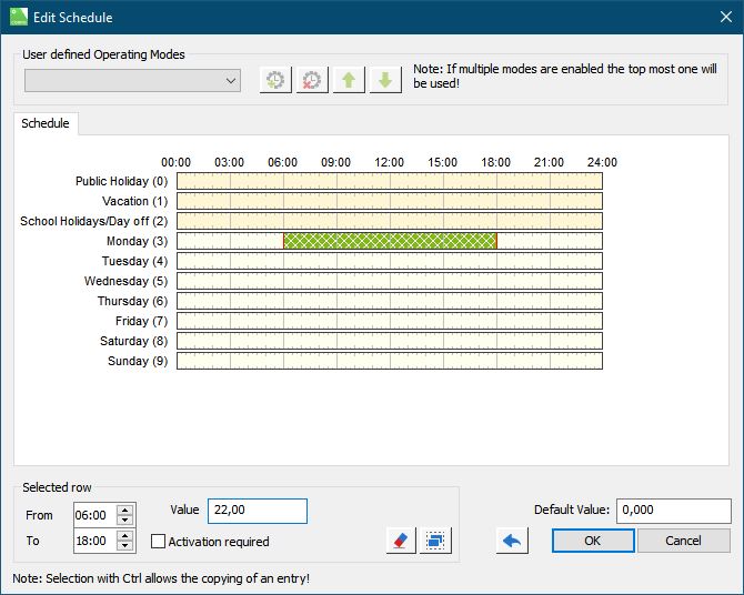
A double click on the block opens the editing window in which the schedule can be set.
By activating remanence (battery symbol), the previous state is restored after a power failure.
Table of Contents
Inputs↑
| Abbreviation | Summary | Description | Value Range |
|---|---|---|---|
| Act | Activate | If 'activation required' is set in an entry, it is only activated with an additional pulse on this input while entry is active. | 0/1 |
| Off | Off / Lock | Pulse (< 200 ms): Outputs are reset / switched off. Pulse (> 200 ms): Block is locked. Dominating input. Pulse (> 500 ms): The name of the connected sensor is used in the user interface. | 0/1 |
| Rtd | Reset to default | Resets parameters and settings of the block to the default values as specified in the block preset. | 0/1 |
Outputs↑
| Abbreviation | Summary | Description | Unit | Value Range |
|---|---|---|---|---|
| O | Output | Digital: 0 or 1 Analog: Default value or value of entry. | - | ∞ |
| Om | Number of active operating mode. | - | ∞ | |
| On | Pulse when On | - | 0/1 | |
| Off | Pulse when Off | - | 0/1 | |
| Rt | Remaining time | Remaining time of a timer started in the user interface. | s | 0...∞ |
| API | API Connector | Intelligent API based connector. Can link several functions between devices and blocks. API Commands | - | - |
Parameters↑
| Abbreviation | Summary | Description | Unit | Value Range | Default Value |
|---|---|---|---|---|---|
| Rem | Remanence input | Remanence input: If active, the function block retains its previous state after a Miniserver reboot. The state of the function block is saved: – When saving to the Miniserver – At a planned reboot – Before a backup – Once per hour The data is saved on the SD card. | - | 0/1 | 0 |
| Am | Automatic mode | 0 = Automatic 1 = Manual via Parameter (Mm) | - | 0/1 | 0 |
| Mm | Manual mode | Set the operating mode manually. | - | ∞ | 0 |
| Don | On-duration of output (O) | If 'activation required' is set, the duration which the value is output on (O) is limited to this time. 0=disabled | s | 0...∞ | 0 |
Properties↑
| Summary | Description | Default Value |
|---|---|---|
| Schedule | Schedules for time-based permission to function blocks used for access control such as the Authentication NFC Code Touch or Access Controller. Changes affect all users and user groups that are configured to use this schedule. | - |
| Use as Digital Output | If checked, the analog output will be used as digital output. | - |
| Description for Active | This text is displayed in the Apps instead of 'Active'. | - |
| Description for Inactive | This text is displayed in the Apps instead of 'Inactive'. | - |
Timer Digital/Analogue↑
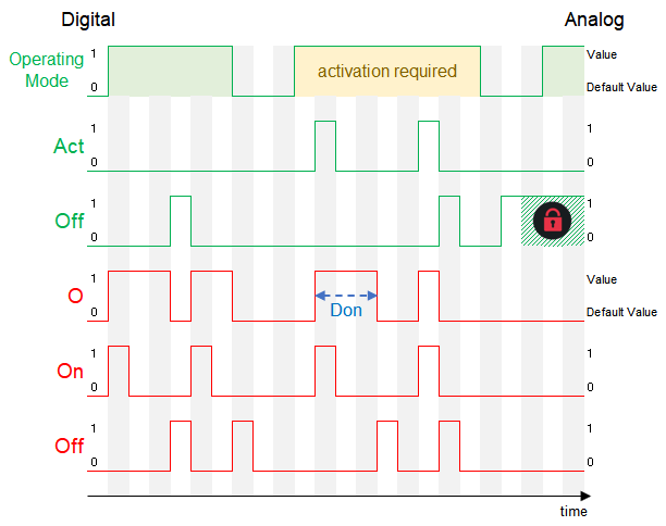
If the timer is used digitally, the output (O) is switched on during the switching time. For analog use, a specific value is output at the output (O) during the switching time.
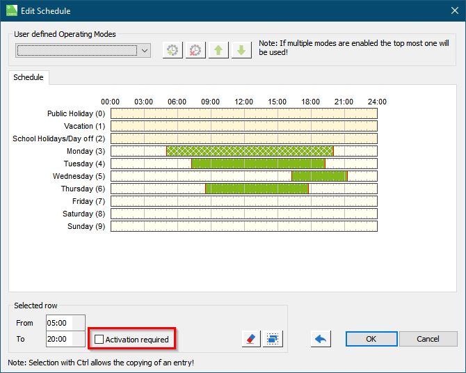
Activation required↑
If the checkbox (activation required) is activated, an additional pulse must be applied to the (Act) input within the switching time to activate (O). If a pulse is applied to the input (Off) within the switching time, the output (O) is deactivated prematurely.
Manual Mode↑
If parameter (Am) is 1, manual mode is activated. If the value of parameter (Mm) changes to 4, the timer will work with the switching time of <Operating Mode>(4).
Timing Diagram↑