With the RGBW Dimmer Tree, extra low-voltage LED fittings and LED strips can be dimmed using PWM and any useable colours can be mixed. The 4 outputs can be configured as one RGBW channel, or can be used as 4 separate channels.
The device is also available in a compact housing (RGBW Compact Dimmer Tree). The functions are identical.
Datasheet RGBW 24V Dimmer Tree
Datasheet RGBW 24V Compact Dimmer Tree
Table of Contents
- Mounting
- Commissioning
- Individual channels
- Smart Tunable White
- Power Limiting Behavior
- Tree Communication and Voltage Drop
- Inputs, Outputs, Properties
- Safety Instructions
- Documents
Mounting↑
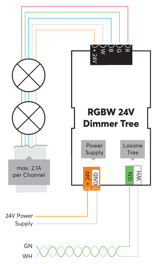
The RGBW Dimmers is installed on a DIN rail in a suitable enclosure. The Compact Dimmer can be used without a separate enclosure. The cable should be kept as short as possible to reduce voltage drop.
The wire size should be selected so that the voltage drop is not more than 1 V. This can be determined using the following formula:
ΔU = I · R = I · ((2 · L · ρ) / A)
I … current [A], L … cable length [m], A … wire cross-section [mm²], ΔU … voltage drop [V], ρ … resistance [( Ω*mm²)/m], ρ= constant (0,0172 for copper)
Connect the power supply and Tree communication wires. Shortly after power-up, the status LED will blink orange if the wiring is correct (connection to Tree Extension and Miniserver is established).
Commissioning↑
Then follow the pairing procedure on the Tree Interface.
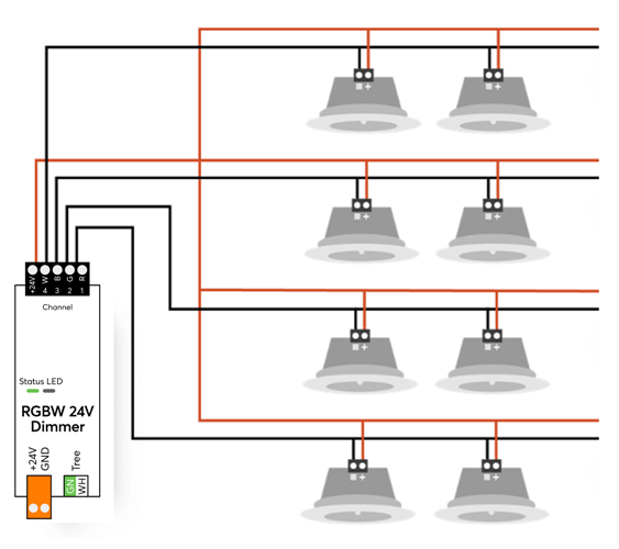
Individual channels↑
If "Individual channels " is selected as actuator type in the properties of the device, the channel assignment is as follows:
Output 1 - Channel Red, output 2 - Channel Green, output 3 - Channel Blue, output 4 - Channel White
Smart Tunable White↑
Tunable White (TW) refers to lighting with white light that is adjustable in color temperature.
For this purpose, light sources such as LED strips are available that combine warm white light and cool white light.
The color temperature can be adjusted from warm white to cool white by mixing the two colors.
For this purpose, Loxone Devices with RGBW Dimming outputs support the actuator type Smart Tunable White:
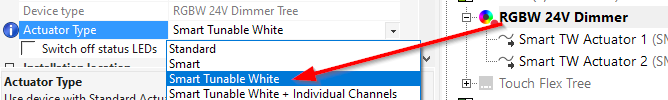
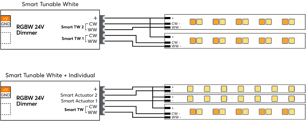
Two outputs of the dimmer for cool white (CW) and warm white (WW) are combined per actuator.
Smart Tunable White actuators are supported by the Lighting Control block.
Two Smart TW actuators or one Smart TW actuator and two individual channels can be configured.
The assignment of the connections is as follows:
In the settings of the Smart TW actuator, the color temperature of the light source is set for warm white and cool white:
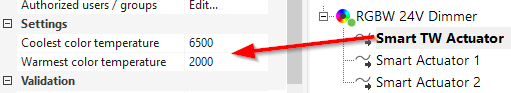
This information can be found in the technical data of the light source.
Power Limiting Behavior↑
RGBW Smart Actuator:
No direct power limiting is applied, each channel is controlled independently according to the RGB colour wheel.
On the TW colour wheel, W is mixed with RGB to simulate cold/warm white.
Smart Tunable White Actuator:
With the Smart Tunable White actuator, the sum of warm white (WW) and cool white (CW) never exceeds the power output of a single channel, regardless of the selected colour temperature mixing ratio.
Standard Actuator:
Simultaneous full control of all 4 channels is only possible with the ‘Standard’/‘Individual Channels’ actuator type, where all 4 outputs are independent of one another.
Tree Communication and Voltage Drop↑
If the current flow on the GND line results in a voltage drop too high, this potential difference also affects the tree communication.
To solve this problem, split consumers of higher power over longer distances to several supply lines, or use a supply line with a higher cross-section, or a power supply close to the consumers.
For existing installations, doubling the cross-section of the GND line is often sufficient to eliminate the potential difference.
Actuators↑
| Summary | Description | Value Range |
|---|---|---|
| Smart actuator RGBW | Smart actuator | ∞ |
Diagnostic Inputs↑
| Summary | Description | Unit | Value Range |
|---|---|---|---|
| Online Status RGBW 24V Dimmer Tree | Indicates whether the device can be reached by the Miniserver. Diagnostics for Air devices Diagnostics for Tree devices Diagnostics for Extensions | Digital | 0/1 |
Properties↑
| Summary | Description | Default Value |
|---|---|---|
| Monitor Online Status | If checked, you will be notified via System Status or the Mailer if the device is no longer available or goes offline. | - |
| Serial Number | Specifies the serial number of the device. Enter 'Auto' to automatically pair a Tree device with unknown serial number. This can only be used if there is only one Tree device of the same type on a standalone Miniserver (not in a Client-Gateway setup). Save in the Miniserver to pair the Tree device. Afterwards the program must be loaded from the Miniserver to transfer the actual serial number of the Tree device into the program. | - |
| Actuator Type | Use device with Standard Actuator(s) or Smart Actuator(s) Smart Actuators support dynamic fade times and can only be used with the Lighting Controller. | - |
| Lighting Group | Assigned Lighting Group. To create a new group simply start typing a name. | - |
| Switch off status LEDs | If checked, the status LEDs on the device are switched off in normal operation. In the event of a fault, the device will continue to alert you to its status LEDs. | - |
Safety Instructions↑
The installation must be carried out by a qualified technician in accordance with all applicable regulations.
The installation requires a suitable enclosure to ensure protection against contact, water and dust.
Documents↑
Datasheet RGBW 24V Dimmer Tree
Datasheet RGBW 24V Compact Dimmer Tree