The Loxone Power Supply & Backup is a DIN-rail mounted power supply for up to 40A. It offers seven outputs providing 24VDC for up to 10A each.
Each output comes with a dedicated fuse and power measurement.
Additionally connect a 36VDC battery to power-backup your Loxone installation in case of power failure. Of course, without interruption.
Datasheet Power Supply & Backup
Table of Contents
- Mounting
- Commissioning
- Connect Batteries
- Replace Fuses
- LED Status
- Bridging Outputs
- Inputs, Outputs, Properties
- Safety Instructions
- Documents
Mounting↑
Mount on a DIN rail in a suitable distribution enclosure with a minimum volume of 100l / 6100 cu in.
Ensure heat dissipation by mounting horizontally in the lower area of the enclosure and providing a 50mm / 2” clearance below and above the unit. Do not cover ventilation openings.
Connect the mains supply, 24V outputs, and the Tree data lines:
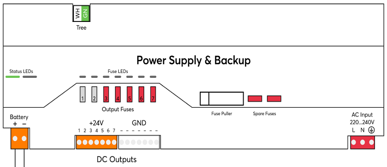
To use the optional backup function, a 36V battery is connected.
The 24V outputs allow the creation of 7 circuits.
The outputs are basically identical, except for the fuses, which can be changed as needed.
From the factory, the first two outputs are equipped with 2A fuses suitable for low power devices.
Recommendation: The first output to supply Miniserver and Extensions in the distribution board, the second one for the peripheral sensors in the building.
The remaining outputs are equipped with 10A fuses, making them suitable for circuits with powerful loads such as lighting and audio.
Select the fuses according to the conductor cross-section used and the load at the respective output.
All GND terminals are already connected internally.
To perform a PELV installation, GND must be connected externally to PE.
The 24V outputs may be bridged under certain conditions.
After completion of the overall installation, the mains voltage supply can be switched on.
Commissioning↑
Then follow the pairing procedure on the Tree Interface.
The configuration of the power supply is done with the Function Block of the same name in Loxone Config.
Drag the power supply from the periphery tree to the programming page to insert the function block.
Connect Batteries↑
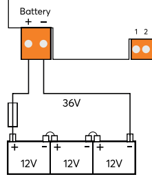
The capacity of a single battery of the series connection must be entered in the settings of the device in Loxone Config.
The charging electronics of the power supply is designed for lead-acid batteries in standby application.
Sealed (VRLA/SLA) Gel or AGM batteries are recommended, which are suitable for this application.
For battery installation and recommended environmental conditions, please follow the instructions of the respective battery manufacturer.
The battery cables and their fuse protection near the battery must be dimensioned according to the technical data (36V/25A) and local regulations. This often results in a cross-section of 4mm² / AWG10 and a slow-acting fuse type with 25A.
Parallel connection of battery packs
Complete 36V battery packs can also be connected in parallel. Again, only packs of the same capacity, type and age may be combined. To set the total capacity, add the capacities of one battery per pack.
Since the currents add up when connected in parallel, the fuse protection of the individual packs is not sufficient in this case. The entire combination must therefore be fused accordingly.
The parallel connection only makes sense for packs with low capacity, where possible a single pack with higher capacity should be preferred.
Each Power Supply & Backup requires its own battery pack!
Connecting multiple Power Supply & Backup units to one battery pack is not permitted!
Battery Charging Procedure
The battery charging process uses the UI characteristic curve method, which ensures efficient and safe charging.
The maximum charging voltage is capped at 40.5 V to maintain the batteries' optimal operating range. This precaution is necessary as the system does not monitor ambient temperature, which could otherwise affect the charging process.
The maximum charging current is limited to 1/10 of the battery nominal capacity, based on the battery specifications. This ensures a controlled and safe charging process that prevents overloading the battery.
The system protects the batteries by automatically shutting down if the voltage drops below 31 V while in backup mode, preventing deep discharge and extending their lifespan.
Replace Fuses↑
If all PSB fuses are red and there is no 24V output, the mains voltage is too low.
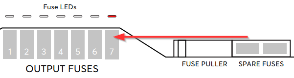
Remove the fuse puller from the front panel and use it to pull out the blown fuse.
 | Before replacing the fuse, ensure that there is no short circuit at the affected output. Contact a qualified electrician or Loxone partner for assistance. If testing is not possible, the fuse replacement must only be carried out when the device is completely de-energized. |
Replacement fuses are located on the right side of the front panel. Replace a blown fuse only with one of the same value / color!
Suitable replacement fuses of the type Littelfuse® 297 are also called automotive flat fuse Mini 32V, APM/ATM, and are available in the Loxone Shop or at Loxone Partners, among others.
The red LED above the fuse should then go out.
If the LED does not go out, or lights up again after a short time, it is due to a short circuit, an overload, or a fuse with too small a current rating was used.
In this case, consult a Loxone partner or qualified electrician.
LED Status↑
| Left LED | Right LED | Description |
|---|---|---|
|
| Everything OK, device is online. |
|
| Connection to the Miniserver is okay, but the device has not been paired. |
|
| Device cannot connect to the Miniserver via the Tree interface. |
|
| Device was selected in Loxone Config and is identifying. |
|
| Update is in progress. |
|
| No battery detected Battery service recommended |
|
| Emergency power supply active Battery almost empty Fuse has failed Thermal shutdown Risk of overheating Battery defective |


If all PSB fuses are red and there is no 24V output, the mains voltage is too low.
Bridging Outputs↑
Bridging (paralleling) the 24V outputs of a Power Supply & Backup is possible under the following conditions:
The bridged outputs must be fused on the device with the same fuse value.
The bridged outputs must be wired symmetrically (same cable length, same cross-section) to ensure the current is evenly distributed.
The conductor cross-section must be sized according to the sum of the nominal currents of the fuses for the bridged outputs.
The same number of GND outputs must be bridged accordingly.
Paralleling outputs from different Power Supply & Backup devices with each other is not allowed!
Diagnostic Inputs↑
| Summary | Description | Unit | Value Range |
|---|---|---|---|
| Fuse 1 | Active when Fuse 1 is blown | - | 0/1 |
| Fuse 2 | Active when Fuse 2 is blown | - | 0/1 |
| Fuse 3 | Active when Fuse 3 is blown | - | 0/1 |
| Fuse 4 | Active when Fuse 4 is blown | - | 0/1 |
| Fuse 5 | Active when Fuse 5 is blown | - | 0/1 |
| Fuse 6 | Active when Fuse 6 is blown | - | 0/1 |
| Fuse 7 | Active when Fuse 7 is blown | - | 0/1 |
| Battery Test | Active while Battery test is running | - | 0/1 |
| Soc | Battery State of charge | % | 0...100 |
| Online Status Power Supply & Backup | Indicates whether the device can be reached by the Miniserver. Diagnostics for Air devices Diagnostics for Tree devices Diagnostics for Extensions | Digital | 0/1 |
| System temperature | Provides the internal device temperature. This is often the temperature of the CPU or another location in the device. | ° | ∞ |
Actuators↑
| Summary | Description |
|---|---|
| API Connector | Intelligent API based connector. API Commands |
Properties↑
| Summary | Description | Unit | Value Range | Default Value |
|---|---|---|---|---|
| Monitor Online Status | If checked, you will be notified via System Status or the Mailer if the device is no longer available or goes offline. | - | - | - |
| Serial Number | Specifies the serial number of the device. Enter 'Auto' to automatically pair a Tree device with unknown serial number. This can only be used if there is only one Tree device of the same type on a standalone Miniserver (not in a Client-Gateway setup). Save in the Miniserver to pair the Tree device. Afterwards the program must be loaded from the Miniserver to transfer the actual serial number of the Tree device into the program. | - | - | - |
| Output-Voltage | Output-Voltage for all outputs | V | 24...27 | 24 |
| Battery-Capacity | Capacity of a single Battery (not Sum of all Batteries). | Ah | 1...200 | 20 |
| Supply Type | Device is used as a power supply. If batteries are connected, the backup function can also be used. | - | - | - |
| Configuration | Configuration of the Inputs and Outputs Used. | - | - | - |
Safety Instructions↑
Installation must be carried out by a qualified electrician in accordance with the applicable regulations.
This device must be mounted on a DIN rail in an electrical distribution enclosure to ensure protection against contact, water and dust.
Only mount the device on a horizontal DIN rail to ensure heat dissipation by convection.
Documents↑
Datasheet Power Supply & Backup