The Nano 2 Relay Tree is a compact module with 2 relay outputs, controlled via the Loxone Tree Technology.
The two relay outputs can either be configured separately or are used together as shading actuators. They are volt-free and therefore suitable for different voltages. The outputs share a common contact.
Table of Contents
Mounting↑
Install the device in a suitable installation box.
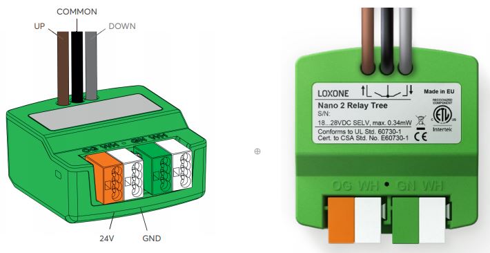
Connect the power supply (orange/white terminal) and Tree communication wires (green/white terminals). Shortly after power-up, the status LED will blink orange if the wiring is correct (connection to Tree Extension and Miniserver is established).
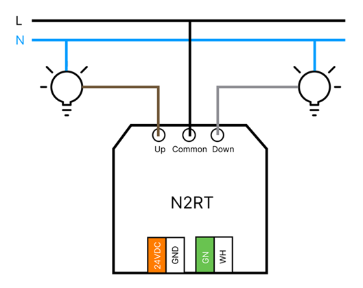
Wiring Example Lighting:
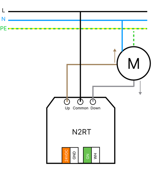
Wiring Example Shading:
Commissioning↑
Then follow the pairing procedure on the Tree Interface.
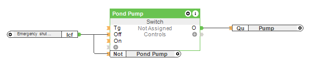
Application Example↑
The Nano 2 Relay Tree has two applications: "Universal" and "Shading". This specifies the intended use of the actuators.
Universal: Outputs and Current Flow can be used freely.
Shading: Auto-Configuration will create an Automatic Shading function block

Sensors↑
| Summary | Description |
|---|---|
| Current Flow | Input is active when current flows through the relay outputs |
Actuators↑
| Summary | Description | Unit | Value Range |
|---|---|---|---|
| Up | Digital relay output 1 | - | 0/1 |
| Down | Digital relay output 2 | - | 0/1 |
| API Connector | Text | - |
Diagnostic Inputs↑
| Summary | Description | Unit | Value Range |
|---|---|---|---|
| Online Status Nano 2 Relay Tree | Indicates whether the device can be reached by the Miniserver. Diagnostics for Air devices Diagnostics for Tree devices Diagnostics for Extensions | Digital | 0/1 |
| System temperature | Provides the internal device temperature. This is often the temperature of the CPU or another location in the device. | ° | ∞ |
| Temperature Shutdown | Input is active, when the outputs of the device have been switched off due to high device temperature. Possible reasons: Ambient temperature too high, outputs overloaded. | Digital | 0/1 |
Properties↑
| Summary | Description | Value Range | Default Value |
|---|---|---|---|
| Monitor Online Status | If checked, you will be notified via System Status or the Mailer if the device is no longer available or goes offline. | - | - |
| Serial Number | Specifies the serial number of the device. Enter 'Auto' to automatically pair a Tree device with unknown serial number. This can only be used if there is only one Tree device of the same type on a standalone Miniserver (not in a Client-Gateway setup). Save in the Miniserver to pair the Tree device. Afterwards the program must be loaded from the Miniserver to transfer the actual serial number of the Tree device into the program. | - | - |
| Application | Specifies the intended use of the actuators. Universal: Outputs can be used freely Shading: Auto-Configuration will create a Automatic Shading function block | - | - |
| Automatically set drive times | Automatically learn travel durations for complete travels (Application: Shading). For learning, perform three uninterrupted complete travels to an end position. Open-close-open or close-open-close. This is not possible for motors with less than 100mA current consumption. In this case, please deactivate the option and set the travel durations in the Shading Block via the parameters (Opd) and (Cld). This function uses the current detection threshold. Set the threshold higher if some current still flows after the motor has stopped running. | - | - |
| Inverted Direction | Invert direction. Required when Up/Down connection is made the wrong way round. | - | - |
| Threshold for current detection [mA] | Current flow is detected when the sum of the current at both outputs exceeds this threshold. This is used depending on the application of the device: - Universal: The Current Flow input can be used in the project. - Shading: Used to determine if the motor is running or not, so the travel durations can be set automatically. | 100...5000 | - |
Safety Instructions↑
The installation must be carried out by a qualified technician in accordance with all applicable regulations.
The installation requires a suitable enclosure to ensure protection against contact, water and dust.