The function block Mixing Valve Controller can be used to control common mixing valve types.
This makes it possible to control the flow temperature in heating systems or similar applications in ventilation and air conditioning systems.
Mixing valves or actuators can be controlled with two digital outputs for opening and closing, or with an analogue value of 0-10.
The setpoint and actual temperature are connected to the block's inputs.
The PI controller of the block calculates the necessary mixing position based on the deviation between the setpoint and actual value, and controls the outputs accordingly.
For applications where cooling is required, the block can be switched to an inverted mode.
Table of Contents
Inputs↑
| Abbreviation | Summary | Description | Unit | Value Range |
|---|---|---|---|---|
| ϑt | Target temperature | ° | ∞ | |
| ϑc | Current temperature | ° | ∞ | |
| Off | Off | Sets output (V) according to parameter (Offm). | - | 0/1 |
| DisPc | Disable periphery control | Disables input (ϑt) when On. (e.g Child lock, cleaning) | - | 0/1 |
Outputs↑
| Abbreviation | Summary | Description | Unit | Value Range |
|---|---|---|---|---|
| V | Valve | Provides signal for 0-10V mixing valve. | V | 0...10 |
| O | Open | - | 0/1 | |
| C | Close | - | 0/1 | |
| Error | Error | Active when difference between current and target temperature exceeds 5°C/9°F for longer than 10 minutes. Error timer is reset and suspended for 15 minutes by reference drive, target temperature adaption or a change at input Off. | - | 0/1 |
| API | API Connector | Intelligent API based connector. Can link several functions between devices and blocks. API Commands | - | - |
Parameters↑
| Abbreviation | Summary | Description | Unit | Value Range | Default Value |
|---|---|---|---|---|---|
| Td | Travel duration mixing valve | s | 0...∞ | 150 | |
| St | Sampling time | Sampling period of controller in seconds. New values for (V), (O) and (C) are calculated by the controller at this time interval. | s | 0...∞ | 40 |
| Kp% | Gain | Controller gain in %, where Kp% = Kp * 100. | % | 0...100 | 2 |
| Ki% | Integral part | Integral part of the controller in %, where Ki% = Ki * 100. | % | 0...100 | 0,03 |
| Offm | Off mode | 0 = Unchanged 1 = Open 2 = Close | - | 0...2 | 2 |
| Mode | Mode | 0 = normal, 1 = inverted (for cooling: mixer opens as the temperature rises) | - | 0/1 | 0 |
| MinP | Minimum Position | % | 0...100 | 0 | |
| MaxP | Maximum Position | % | 0...100 | 100 | |
| Inv | Invert | 0 = normal, 1 = analog output is inverted (0V = 100%, 10V = 0%) | - | 0/1 | 0 |
| Vs | Valve standstill | Maximum actuator standstill in days. If the valves have not operated in set time, they will be moved automatically. Time should be set as specified by the manufacturer! 0 = function is disabled. | d | ∞ | 14 |
Properties↑
| Summary | Description | Default Value |
|---|---|---|
| Use for System Status Messages | If this box is ticked, an error message will be sent from this input via the mailer and the system status. | - |
Programming example↑
The following example shows the basic programming of the block:
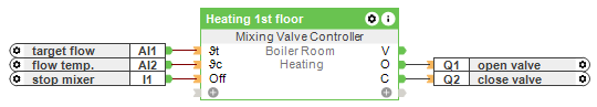
The block is provided with the setpoint value at input (ϑt) and the actual value for the flow temperature at input (ϑc). Relay outputs for controlling the mixing valve are connected to the outputs..
In addition, the block can be stopped via the (Off) input when it is not in use.
Usually the block is used in combination with other blocks and logic, and further devices like pumps have to be controlled.
The following picture shows an example:
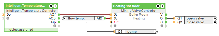
In this example, the Flow Temperature Calculator determines and transmits the setpoint value for the flow temperature, and switches the Mixing Valve Controller and circulation pump on and off together. The (Off) input of the mixing block is inverted for this purpose.
Please note that further logic must be added here if mixing valves or pumps may only operate under certain conditions.
Calibration run↑
Whenever the mixing valve is moved to an end positions (0 or 100%), the respective digital output is activated for 1.2 times the mixing valve runtime.
This calibration run ensures that the end position is definitely reached and that the calculated position corresponds to the actual position.