OVERVIEW
When using LED strips there are two main options that are available, RGBW and Warm White. RGBW gives the opportunity to have full colour spectrum control. LEDs by their nature don’t work at 230V so there measures put in place to convert it. However by dropping down to 24V we avoid any of issues of 230V. One of the main reasons for using 24V is cost, dimming mains voltage LEDs requires much more expensive hardware in comparison to that needed for dimming at 24VDC. This difference can be up to 1/3 of the cost. In addition to this quality of the dimming and the huge reduction in inrush current make 24V lighting our choice when it comes to not just LED Strips but also when looking at LED Spot lighting.
This information is in relation to the Loxone articles 200043, 200061, 200092.
View Datasheet >>
REQUIRED PRODUCTS
- Warm White LED Strip or RGBW LED Strip
- This information is in relation to the Loxone articles 200043, 200061, 200092.
- View Datasheet >>
- RGBW 24V Dimmer Tree
- Tree Extension
- 24VDC Power Supply
- Touch Tree or Touch Pure Tree
- Motion Sensor Tree
- CAT7 Cable
*In addition to a Miniserver
WIRING
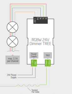
In a new build property the RGBW 24V Dimmer Tree is located in the main cabinet along with the Miniserver, Tree Extension and PSUs. From that location the appropriate cable is taken from the RGBW 24V Dimmer Tree to the strip, be it a RGBW or a Warm White one. Suggested cable from RGBW 24V Dimmer Tree to LED Strip:
- RGBW Spot – 5-core Flex
- Warm White – Twin and Earth
The core thicknesses of cable that you use will be defined by both building regulations and the load/distance over which the cable will be run, thus these must be calculated for your particular project.
The voltage drop can be calculated using the following formula: ΔU = I · R = I · ((2 · L · ρ) / A)
I … Current [A]
L … Cable Length [m]
A … Cable Cross-Section [mm²]
ΔU … Voltage Drop [V]
ρ … Material Specific Resistance [( Ω*m)/mm²] ρ= 0.0172 (for Copper)
For technical documentation on the RGBW 24V Dimmer Tree click here.
The RGBW 24V Dimmer Tree can be used in two forms to allow it to control either single colour Warm White LED Strips, these two modes are referred to as “Individual dimming channels” or “RGBW dimming”. The common terminal on the RGBW Dimmer Tree is the +24V meaning that we are dimming on the -ve side. If “Individual dimming channels” is selected as PWM configuration in the properties of the device, the channel assignment is as follows:
Red -> Dimmer 1
Green -> Dimmer 2
Blue -> Dimmer 3
White -> Dimmer 4
For “RGBW dimming” we need to use all 4 channels in order to have full RGBW (Red, Green, Blue, White) control on each circuit. In the diagram below we can see how each RGBW LED Strip is connected with each channel wired in parallel.
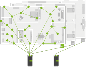
Wiring for the Motion Sensor Tree and Touch/Touch Pure Tree couldn’t be simpler. These two devices require a Tree connection and a 24VDC power supply that is provided on a CAT7 cable. The topology of Tree allows you to run almost any network except a complete loop and save up to 80% on cabling over a basic STAR wiring layout, see below image for an example.
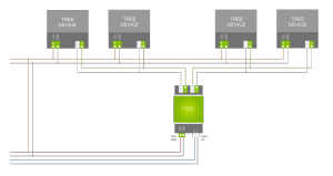
The RGBW Dimmer Tree, Motion Sensor Tree and Touch/Touch Pure Tree all simply need a Tree connection and a power supply as per the below diagram.
![]() If you are unsure at any point when wiring up any of our devices, please contact a suitably qualified electrician. Alternatively you can contact us for more technical data if required.
If you are unsure at any point when wiring up any of our devices, please contact a suitably qualified electrician. Alternatively you can contact us for more technical data if required.
DESIGN CONSIDERATIONS
When designing a key thing to consider is the overall loading for the system. This effects how many RGBW Dimmers required, how many and of what type power supply is required and as per above what cable thickness will be needed to cope with the load.
CONFIGURE TREE DEVICE
 For information on how to connect your Tree Device with Loxone config then click here!
CONFIGURE LIGHTING CONTROLLER