The function block Flow Temperature Calculator calculates the flow temperature based on the outside temperature and the integrated heating curve, as well as the energy requirements of the assigned rooms.
It determines the heating or cooling requirements of all rooms of a mixing circuit and enables the control of mixing valves and pumps.
Depending on the set mode, the block's calculations are based on a heating curve or a cooling curve.
Table of Contents
Inputs↑
| Abbreviation | Summary | Description | Value Range |
|---|---|---|---|
| ϑo | Outdoor Temperature | Analog input for the current outdoor temperature. If this input is not connected, the System Variable "Outdoor Temperature" is used. If this value is not available, 0° will be used for calculation, and the value -1000 is displayed on this input. | ∞ |
| Ib | Boost | Digital Input - Boosts the manifold operation. When ON: - During Heating: The maximum target flow temperature (Parameter Max) is put out on output AQf - During Cooling: The minimal target flow temperature (Parameter Min) is put out on output AQf | 0/1 |
| St | Stop | STOP Input - Switches Qp Off - During Heating: The minimal target flow temperature (Parameter Min) is put out on AQf and AQb - During Cooling: The maximum target flow temperature (Parameter Max) is put out on AQf and AQb | 0/1 |
| Tb | Buffer Temperature | Current buffer temperature If connected, activates the mixing valve or pump (output Qp) once the buffer reaches the setpoint temperature (AQb + B for heating, AQb - B for cooling). | ∞ |
Outputs↑
| Abbreviation | Summary | Description | Value Range |
|---|---|---|---|
| AQt | Room target temperature | Room target temperature of the room with the highest (heating) or lowest (cooling) required target flow temperature | ∞ |
| TxQr | Room name | Text output - name of the room with the highest (heating) or lowest (cooling) target flow temperature This output is only visible in certain configurations. | - |
| AQf | Flow target temperature | ∞ | |
| AQb | Buffer target temperature | ∞ | |
| Qp | Manifold demand | Signals manifold demand for mixing valve or pump control. Becomes active once the valve opening of at least one room exceeds the switch-on threshold. If input Tb is connected, Qp activates once the buffer reaches the setpoint temperature (AQb + B for heating, AQb - B for cooling). | 0/1 |
| AQr | Heating / cooling unit requirement | Heating / Cooling Unit Requirement in °Cm² The heating and cooling demand of each room are added up as follows: Temperature difference * room size | ∞ |
| AQl | Heating / cooling load | Heating / Cooling Load (0-100%) The heating and cooling load of each room are added up as follows: Demand of room * Area of room / Total Area | ∞ |
| AQi | Flow temperature increase / decrease | Flow Temperature Increase / Decrease Current increase of flow temperature during heating, or decrease during cooling | ∞ |
| Qe | Error | Error output (invalid values) | 0/1 |
| API | API Connector | Intelligent API based connector. Can link several functions between devices and blocks. API Commands | - |
Parameters↑
| Abbreviation | Summary | Description | Unit | Value Range | Default Value |
|---|---|---|---|---|---|
| Min | Minimum | Minimum flow setpoint temperature The outdoor temperature of input ϑo or system variable is required to calculate the flow temperature. | - | ∞ | 5 |
| Max | Maximum | Maximum flow setpoint temperature The outdoor temperature of input ϑo or system variable is required to calculate the flow temperature. | - | ∞ | 40 |
| B | Buffer Target Temperature Offset | Parameter - Buffer target temperature offset (increase for heating, decrease for cooling) | - | ∞ | 5 |
| S | Slope | Slope of the heating or cooling curve | - | ∞ | 0,5 |
| N | Offset | Parallel shift of the heating curve or cooling curve (When heating, the flow setpoint temperature is increased by this value, when cooling it is decreased) | - | ∞ | 0 |
| Str | Switch-On Threshold | Switch-on threshold in % Only if the valve position of at least one room exceeds this value, the pump (Qp) is enabled If all Room Controllers of an assigned Heating and Cooling Controller/HVAC Controller are used, this parameter has no effect. The Heating and Cooling Controller's switch-on threshold of applies in this case. | - | ∞ | 35 |
| G | Gain | Gain of the room temperature difference Sets with what gain the room temperature difference is weighted (default value = 1) | - | ∞ | 1 |
| I | Target temperature increase / decrease | Target room temperature increase for heating, or target room temperature decrease for cooling. | - | ∞ | 2 |
| Ps | Pump standstill | Maximum pump standstill in days. If the pump was not activated in set time, it will be activated automatically at 2 a.m. for 3 minutes. Time should be set as specified by the manufacturer! | d | ∞ | 0 |
Properties↑
| Summary | Description | Default Value |
|---|---|---|
| Controller for | Select Heating or Cooling loop | - |
| Assignments | Assignment of Intelligent Room Controllers. Based on the request of all configured Room Controllers, flow and buffer temperatures, and other output values are calculated. | - |
Programming example↑
The following example shows the basic programming of the block:
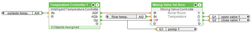
The block is provided with the outdoor temperature at input ϑo. The output AQf is used to transmit the flow setpoint temperature to the Mixing Valve Controller block.
The Mixing Valve Controller and the relay output for the circulation pump are controlled together via the output Qp.
Please note that further logic must be added here if mixing valves or pumps may only operate under certain conditions.
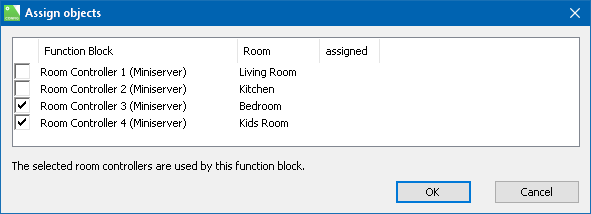
The window that opens when you create or double click on the block is used to assign rooms to the controller.
Here, all rooms that are supplied by this mixing circuit are selected. An Intelligent Room Controller must be available per room:
Whether the mixing circuit is used for heating or cooling is specified in the block settings:
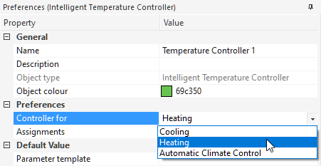
Here you can also set whether the heating/cooling decision is determined by the Heating and Cooling Controller. For this, a Heating and Cooling Controller must be assigned in the field below.
Functional Description↑
To determine the flow setpoint temperature all assigned rooms are analyzed.
When in heating mode, only the rooms that are currently also in heating mode are considered. In cooling mode, only the rooms in cooling mode.
The following values are included in the calculation:
Outdoor temperature
Room target temperature
Deviation room target temperature and actual temperature
Room heating phase / cooling phase
Heating curve or cooling curve
Block parameters
The block first determines the required flow setpoint temperature of each room, then the highest (for heating) or lowest (for cooling) calculated flow setpoint temperature is provided at output AQf.
If there is no heating or cooling demand, the minimum (parameter Min) flow setpoint temperature is provided at output AQf for heating and the maximum flow setpoint temperature (parameter Max) for cooling.
The H/C/HC outputs (valve opening 0-100%) of the assigned room controllers are used for enabling the pump/mixing valve.
If at least one room exceeds the minimum valve opening (specified by parameter Str), output Qp is activated.
The buffer target temperature is above (heating) or below (cooling) the flow setpoint temperature by the value set in parameter B. The value is provided at output AQb.
Calculation examples↑
The following examples show how the flow setpoint temperature is calculated in detail:
Room target temperature:
The heating curve or cooling curve integrated in the block takes into account the room target temperature in addition to the outside temperature. The following applies for both heating and cooling at equal outside temperatures: increasing the room target temperature results in an increase of the flow target temperature.
Example 1: Room target temperature = 20 °C; outdoor temperature = 0 °C (S = 0.5; N = 0) ⇒ flow target temperature = 30.9 °C
Example 2: Room target temperature = 22 °C; outdoor temperature = 0 °C (S = 0.5; N = 0) ⇒ flow target temperature = 33.8 °C
Room temperature deviation:
The room temperature deviation is added (for heating) or subtracted (for cooling) to the room target temperature and used as a corrected room target temperature for the heating or cooling curve.
Parameter G determines the factor by which the room temperature deviation is weighted. By default, G is set to 1. If G is set to 0, the room temperature deviation has no influence on the room target temperature or the flow setpoint temperature.
Example 1: Heating; room target temperature = 20 °C; room temperature deviation = 1.5 °C; G = 1 ⇒ the corrected room target temperature is 21.5 °C
Example 2: Cooling; room target temperature = 20 °C; room temperature deviation = 1.5 °C; G = 2.0 ⇒ the corrected room target temperature is 17.0 °C
Heating or cooling phase:
If a room is currently in the heating phase or cooling phase (e.g. when switching from economy temperature to comfort temperature), the room target temperature is increased or decreased by an adjustable value (see parameter I).
This room target temperature increase or decrease results in a shortened heating or cooling duration.
If parameter I is set to 0, the heating or cooling phase has no influence on the flow setpoint temperature in the temperature control.
Notes↑
Cooling: When cooling, it is important that the flow temperature does not fall below the dew point temperature (condensation). This can be ensured by setting the Min parameter accordingly.
In addition, it is recommended to increase the room target temperatures when the outside temperature rises in order to prevent the rooms from cooling too much on very hot days.