Motor control for garage or gate using one or two buttons
With the Garage and Gate Function Block, various garage doors or gates can be controlled and integrated into the Loxone system.
Select the type of control (Garage or Gate) in properties to ensure the correct animation is used.
The right type of control for the gate must be used. The outputs Tg, Op, and Cl simulate pressing a key on a controller or keyfob.
Use the output (Tg) if its gate or garage control has only one connection for one button (toggle). Use the outputs (Op) and (Cl) if there is a discrete connection for each opening and closing
Direct control is used when the motor is directly connected to outputs from Loxone products (similar to a blind motor)
Table of Contents
Inputs↑
| Abbreviation | Summary | Description | Value Range |
|---|---|---|---|
| Tg | Toggle | Toggles between open, stop, close. For single button control. | 0/1 |
| Co | Complete open | If in motion, stops. | 0/1 |
| Cc | Complete close | If in motion, stops. | 0/1 |
| T5 | T5 control | Button 1: Complete open Button 4: Complete close | ∞ |
| Io | Is open | Input is used to report the “fully opened” position via a limit switch or similar. | 0/1 |
| Ic | Is closed | Input is used to report the “fully closed” position via a limit switch or similar. | 0/1 |
| Off | Off / Lock | Pulse (< 200 ms): Stops movement. Pulse (> 200 ms): Block is locked. Dominating input. Pulse (> 500 ms): The name of the connected sensor is used in the user interface. | 0/1 |
| Spo | Sensor prevent opening | If active, opening is prevented but closing is still possible. Used to connect a photoelectric sensor or similar. | 0/1 |
| Spc | Sensor prevent closing | If active, closing is prevented but opening is still possible. Used to connect a photoelectric sensor or similar. | 0/1 |
| DisPc | Disable periphery control | Disables inputs Tg, Co, Cc, T5 when On. (e.g Child lock, cleaning) Control via user interface is still possible. | 0/1 |
| Po | Partially Open | Moves Gate to partially open position if current position is different. | 0/1 |
Outputs↑
| Abbreviation | Summary | Description | Value Range |
|---|---|---|---|
| Tg | Pulse to Open/Stop/Close | This output is only visible in certain configurations. | 0/1 |
| Op | Open | 0/1 | |
| Cl | Close | 0/1 | |
| Im | In motion | 0/1 | |
| Pos | Position | 0.0 = closed, 1.0 = open | 0...1 |
| Wl | Warning light | For activating a flashing warning light when the gate is moving. On/Off time is defined via parameters (Wlon) and (Wloff). | 0/1 |
| API | API Connector | Intelligent API based connector. Can link several functions between devices and blocks. API Commands | - |
Parameters↑
| Abbreviation | Summary | Description | Unit | Value Range | Default Value |
|---|---|---|---|---|---|
| Rem | Remanence input | Remanence input: If active, the function block retains its previous state after a Miniserver reboot. The state of the function block is saved: – When saving to the Miniserver – At a planned reboot – Before a backup – Once per hour The data is saved on the SD card. | - | 0/1 | 0 |
| Opd | Opening Duration | s | 0...∞ | 60 | |
| Cld | Closing Duration | s | 0...∞ | 60 | |
| Pd | Pulse duration | Pulse duration of outputs Tg, Op, Cl. This parameter is only visible in certain configurations. | s | 0...∞ | 0,5 |
| Ppd | Pulse pause duration | Pause duration between two subsequent pulses of outputs Tg, Op, Cl. This parameter is only visible in certain configurations. | s | 0...∞ | 0,5 |
| Mld | Motor lock duration | Duration of motor lock between direction changes. | s | 0...∞ | 0,5 |
| Wlon | Warning light on duration | s | 0...∞ | 1 | |
| Wloff | Warning light off duration | s | 0...∞ | 1 | |
| Type | Type | Animation Type 0 = Garage Door 1 = Single Gate opening to the left 2 = Single Gate opening to the right 3 = Gate opening to both sides 4 = Folding Door opening to the left 5 = Folding Door opening to the right | - | 0...5 | 0 |
| PoPos | Partially Open Position | Target Position for Input Po. 0.2 = 20% open | - | 0...1 | 0,2 |
Properties↑
| Summary | Description | Value Range | Default Value |
|---|---|---|---|
| Connection Type | Sets the behaviour of the outputs (Tg), (Op) and (Cl) Direct Control = Digital Outputs Separate Controller = Pulse Outputs | - | - |
| Number of activity entries | Number of entries in the activity log. 0: log is disabled The activity log tracks relevant changes since program start. | 0...100 | 20 |
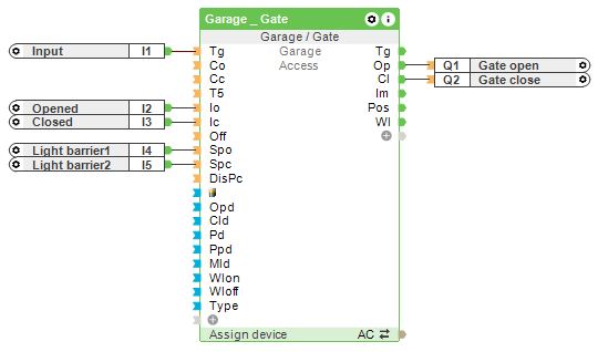
Connection Type: Direct↑
In this configuration, the outputs (Op) and (Cl) operate as on/off signals using two relay outputs, one for opening and one for closing.
Travel times are defined via parameters (Opd) and (Cld). The gate type can be set via the Type parameter for correct display in the user interface and limit switches or light barriers can be connected to the inputs.
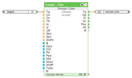
Connection Type: Separate Controller↑
In this configuration, the outputs (Op) and (Cl) operate as pulse signals, with an optional (Tg) output for single-relay control.
Travel times are defined via parameters (Opd) and (Cld). The gate type can be set via the Type parameter for correct display in the user interface and limit switches or light barriers can be connected to the inputs.
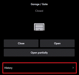
History↑
In the user interface, the history of the function block can be displayed.
A maximum of 100 entries can be shown.
When you restart or save to the Miniserver, the history is cleared.