The Fröling Extension is designed to integrate Fröling heating systems.
Integration is possible beginning with the Fröling Control 3200, version 5.11.
For this, "Modbus Protocol RTU(1)" and "Use Modbus Protocol 2014" must be activated on the controller (Boiler menu).
This setting can be accessed in the controller's service level menu (code -7).
Supported sensors:
Error signal for pellet heating systems, error signal contact for wood chip heating systems
Status of heater circulation pumps
Door contact switch
Boiler, exhaust, outside temperature
Operating hours
Residual oxygen content
Target + actual flow temperature
Boiler + buffer temperature
Buffer charging state
Supported actuators:
Heating circuit activation
Target temperature boiler
Target flow temperature
Table of Contents
- Commissioning
- Setting and using sensors and actuators
- Inputs, Outputs, Properties
- Safety Instructions
- Documents
Commissioning↑
The Fröling Extension is installed on a DIN rail in a suitable enclosure.
Connect the power supply and Link communication to the Miniserver.
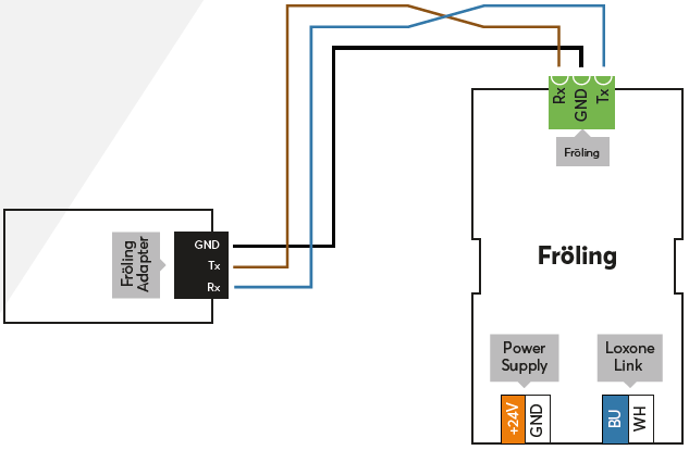
Connect the Fröling controller to the interface as shown in the example above. An adapter is included with the Extension.
 | The interface of the Fröling control has earth potential at GND. In order to avoid potential differences, GND must be connected from the Fröling Extension to the Fröling control. Furthermore, the Loxone installation must also be grounded at GND, this is done directly at the power supply. |
The Extension starts after switching on the power supply, and the status LED will flash orange after a short time when the connection to the Miniserver is established.
Then follow the pairing procedure on the Link Interface.
Setting and using sensors and actuators↑
After pairing the Extension, the supported sensors and actuators are available in the Periphery Tree:
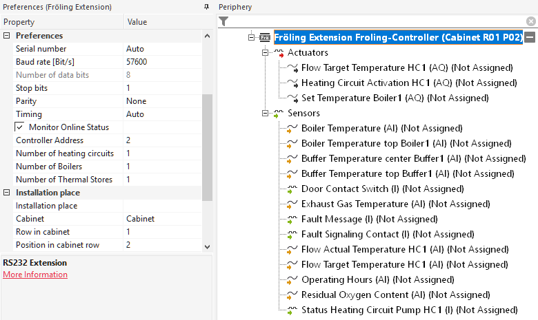
First set the control address (default: 2), as well as the number of heating circuits, boilers and storage tanks.
By default, sensors and actuators are inserted for only one heating circuit, boiler and buffer tank. You can create additional actuators and sensors with Add Fröling Device, and then assign the intended function in the settings of the actuator/sensor:
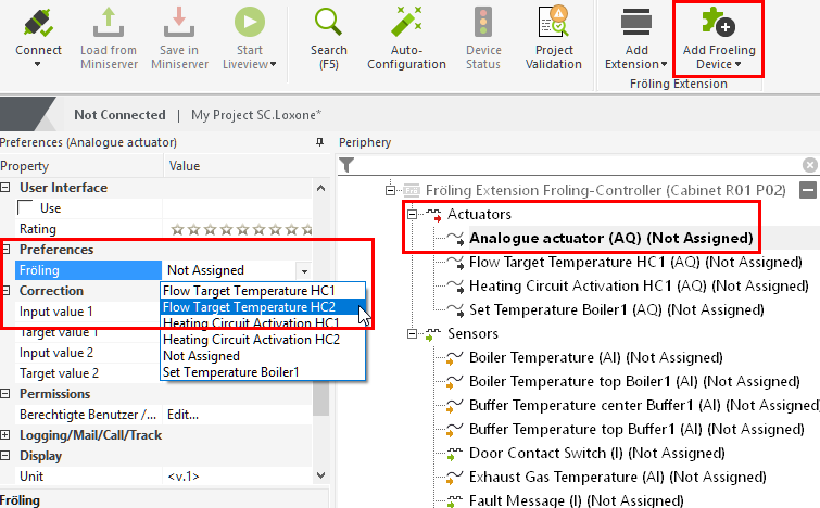
These can then be used in the programming.
It is thus possible to specify the flow temperatures of the heating circuits as well as the boiler setpoint temperatures. Heating activation starts the heating process. If only one heating circuit or boiler is controlled, i.e. a value is written into the corresponding Modbus register, then all other components must also be provided with the corresponding values. If no values are specified, they will be inactive.
Default Actuators
When a Fröling Extension is added, 3 actuators are automatically created for the boiler and flow setpoint temperature, as well as activation of the heating circuit.
These automatically send commands to the Fröling control unit, even if the actuators are not inserted on the program page. This causes the Fröling control unit to switch to “external request” mode.
If this is not desired because only values are to be read from the Fröling control unit, these standard actuators must be deleted from the periphery tree so as not to influence the Fröling control unit.
Diagnostic Inputs↑
| Summary | Description | Unit | Value Range |
|---|---|---|---|
| Online Status Fröling Extension | Indicates whether the device can be reached by the Miniserver. Diagnostics for Air devices Diagnostics for Tree devices Diagnostics for Extensions | Digital | 0/1 |
Properties↑
| Summary | Description | Unit | Value Range | Default Value |
|---|---|---|---|---|
| Serial Number | Specifies the serial number of the device. Enter 'Auto' to automatically pair an Extension with unknown serial number. This can only be used if there is only one Extension of the same type on a standalone Miniserver (not in a Client-Gateway setup). Save in the Miniserver to pair the Extension. Afterwards the program must be loaded from the Miniserver to transfer the actual serial number of the Extension into the program. | - | - | - |
| Baud Rate | Baud rate in bits per second for the serial connection | Bit/s | 0...2147483647 | 57600 |
| Number of data bits | Number of data bits of the serial connection. The extension supports only 8 data bits. | - | 8...8 | 8 |
| Stop Bits | Number of stop bits used (1-2) for the serial communication | - | 1...2 | 1 |
| Parity | Parity for Modbus connection. Stop bits are set automatically: 2 Stop Bits for Parity None, 1 Stop Bit for other settings. | - | - | - |
| Timing | In Auto mode the following timing is used: Pause: 5ms when the baud rate is smaller than 7000bps, otherwise 50bit periods are used. Timeout: 1000ms | - | - | - |
| Monitor Online Status | If checked, you will be notified via System Status or the Mailer if the device is no longer available or goes offline. | - | - | - |
| Controller Address | Address of the Controller Allowed values: 1-255 Default: 2 | - | 0...255 | - |
| Number of heating circuits | Number of heating circuits in this installation Permitted values are 0-18 | - | 0...18 | 1 |
| Number of Boilers | Number of boilers in this installation Permitted values are 0-8 | - | 0...8 | 1 |
| Number of Thermal Stores | Number of thermal stores in this installation Permitted values are 0-4 | - | 0...4 | 1 |
Safety Instructions↑
Installation must be carried out by a qualified electrician in accordance with the applicable regulations.
This device must be mounted on a DIN rail in an electrical distribution enclosure to ensure protection against contact, water and dust.