Why?
If you have an AC or HVAC system that doesn’t have native integration, using the Cool Automation CoolMasterNet you can bring the control of many AC or HVAC systems into Loxone to enjoy the benefits of great Climate Control that Loxone offers. CoolMasterNet allows you to control air conditioning units with Modbus or Modbus IP. It enables seamless and universal integration with any VFF or VRV HVAC system and allows control of multiple indoor units from outdoor units.
Hardware:
- Loxone Miniserver (any version)
- Modbus Extension (Optional)
- Loxone hardware with a temperature sensor in each area you are controlling, such as:
How:
This guide will assume you are comfortable with the installation, commissioning and configuration of the Miniserver and any other applicable Loxone hardware and general configuration of function blocks.
It will also assume you have already wired the outdoor unit(s) to the CoolMasterNet.
Step 1: Connecting the CoolMasterNet to the outdoor unit
Refer to the CoolMaster document found here: https://coolautomation.com/wp-content/uploads/sites/2/2021/01/CoolMasterNET-installation-manual-3.5_.pdf for detailed instructions. DIP switches must be set appropriately for the HVAC units in use, then the outdoor unit comms line must be connected to the CoolMasterNet (only certain comms lines can be used for certain brands, please refer to the linked document above for more information). The images in this guide are for a Samsung outdoor unit.
Step 2: Detecting the indoor units and assigning VAs (Virtual Addresses)
As the CoolMasterNet is capable of controlling multiple indoor units, to be able to offer a control mechanism over Modbus it assigns a Virtual Address to each indoor unit and then uses this address as the base address for the Modbus register of that unit. The CoolMaster is capable of scanning a particular line and detecting all the indoor units connected to it.
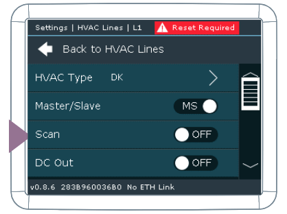
Setting the correct HVAC brand
-
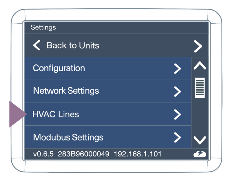
- Go to Settings

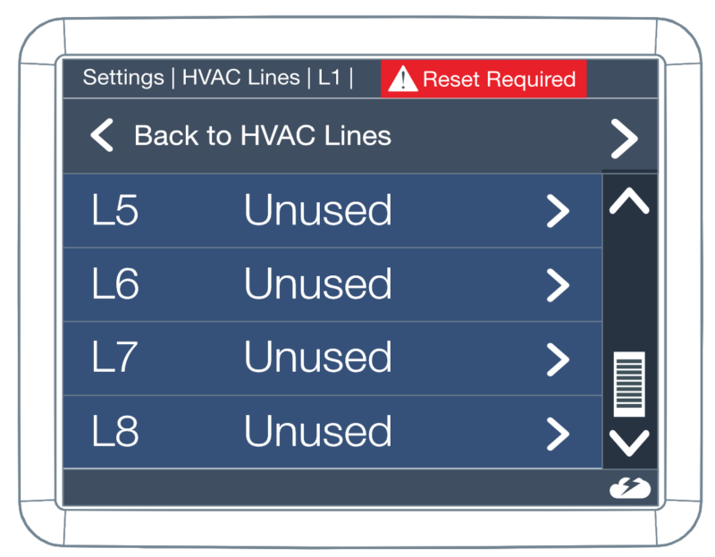
- Go to HVAC Line
- Select the HVAC Line you want to configure
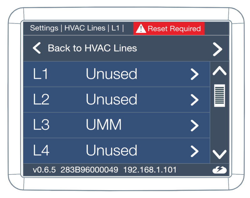
- Configure the HVAC Line type

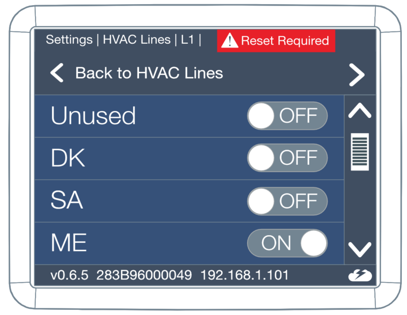
- Make sure the DIP switches are set properly for the brand (according to the details in the brand relevant section above) – (you will have a red warning message if DIP switches are set incorrectly)
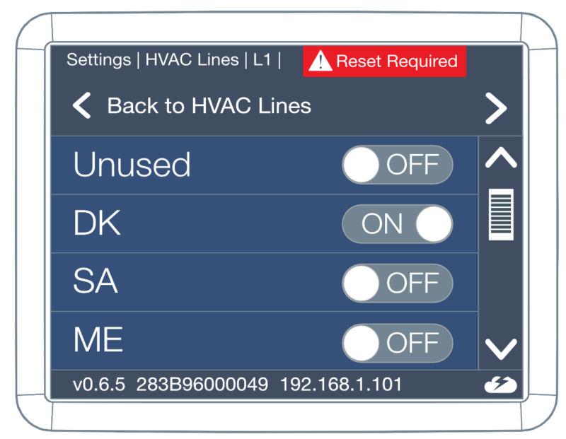
- Reset is required to make the change
- Go to Settings
Scanning for indoor units
-
- Go to Settings
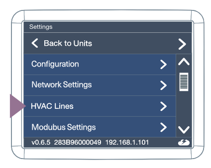
- Go to HVAC Line
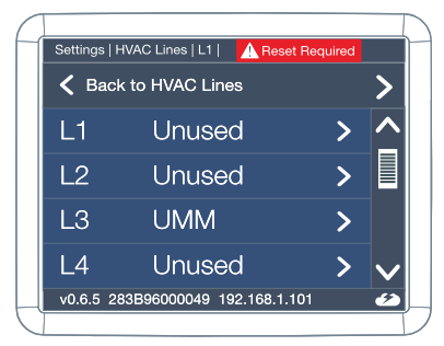
- Select the HVAC Line you want to configure
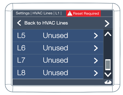
- Press Scan
- Go to Settings
Enabling Modbus IP (Only necessary if not using the Modbus Extension)
-
- Go to Settings
- Go to BMS Settings
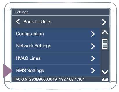
- Enable Modbus IP
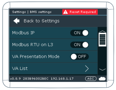
- Go to Settings
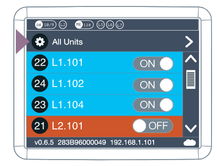
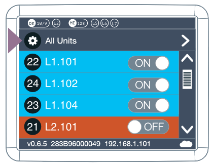
Creating VA (Virtual Address) list
-
- Run VA Auto
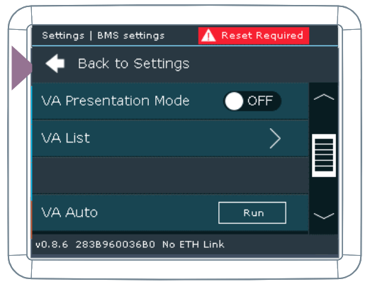
- View VA List
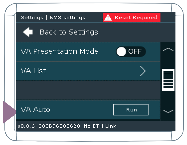
- Run VA Auto
Step 3: Configuration in Loxone Config
If you are using a Modbus Extension, skip to step 2.
Add a Modbus server.
-
- Click on the Network Periphery from the Periphery list
- Click Add Network Device from the top ribbon
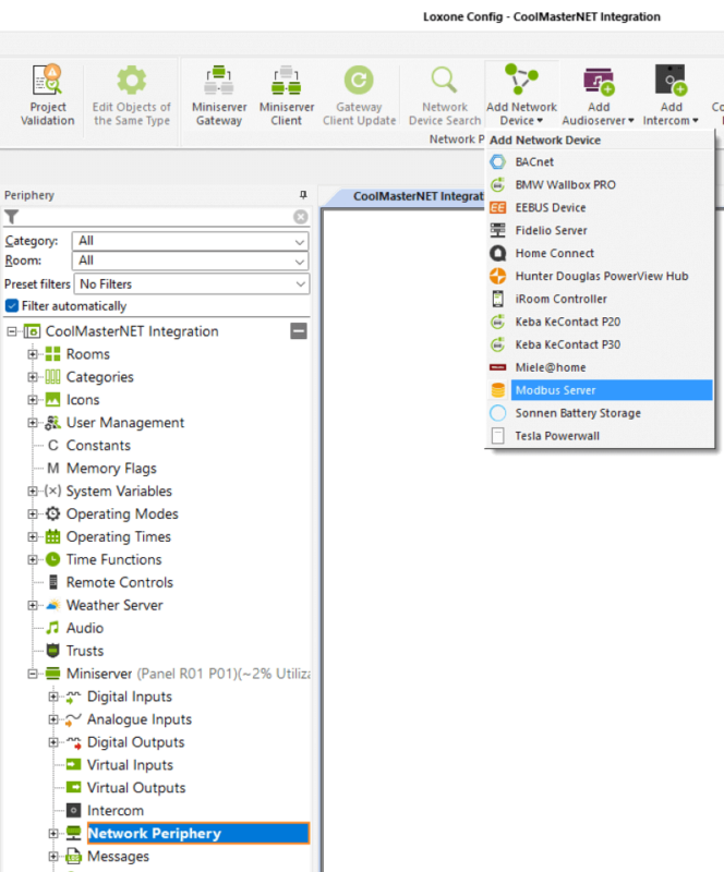
- Select Modbus Server from the list
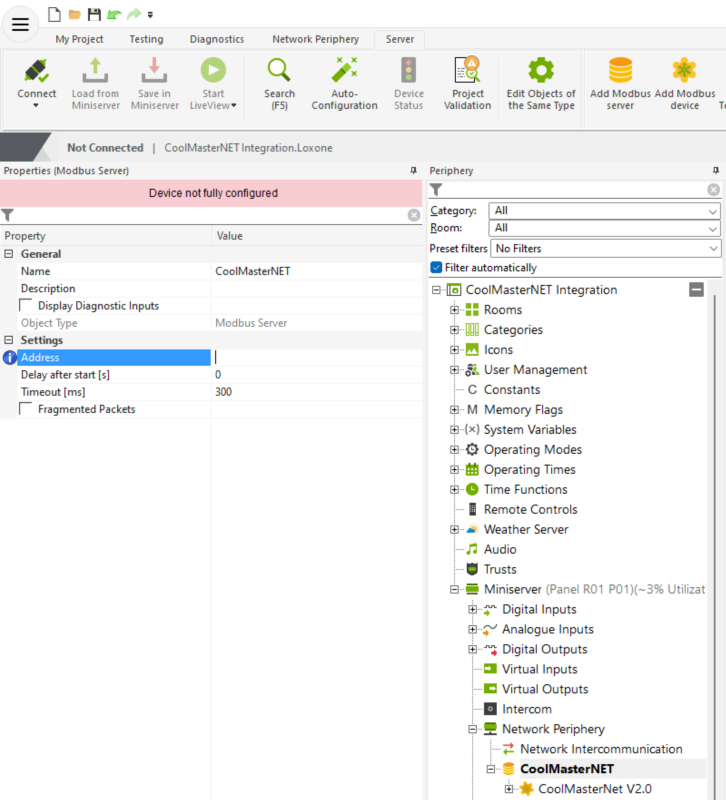
- Input the IP address of the CoolMasterNet unit within the Address field in the Property pane
Skip to step 3 if you are using Modbus IP.
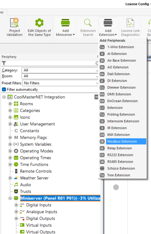
Add a Modbus Extension
- Click on your Miniserver in the Periphery Tree
- Click on Add Extension in the top ribbon
- Click on Modbus Extension
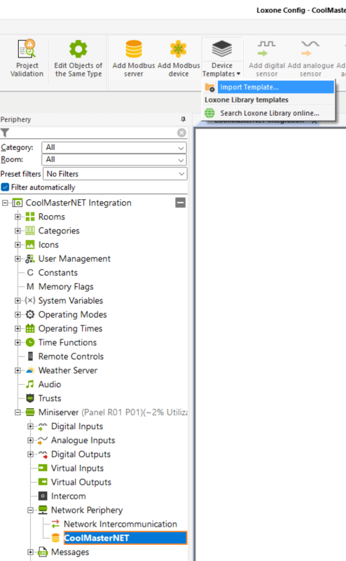
Import Device Template downloaded from https://library.loxone.com/detail/coolmasternet-255/overview
-
- Click on the Modbus server/Modbus Extension you added
- Click on the Device Templates drop down from the top ribbon
- Click Import Template and find the downloaded template on your computer
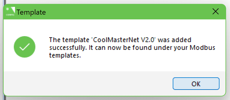
- You will receive a popup confirming the template was added successfully
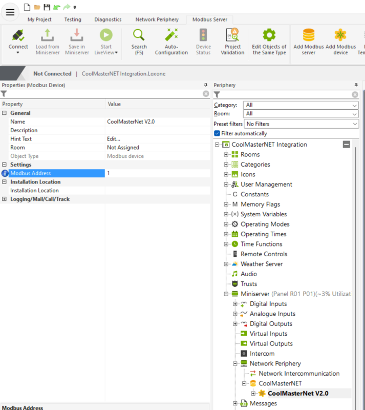
- Click on the Device Templates drop down again from the top ribbon and select the CoolMasterNet template
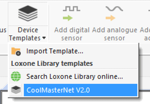
- The default Modbus Address is 1, however this can be adjusted in the Modbus Address field
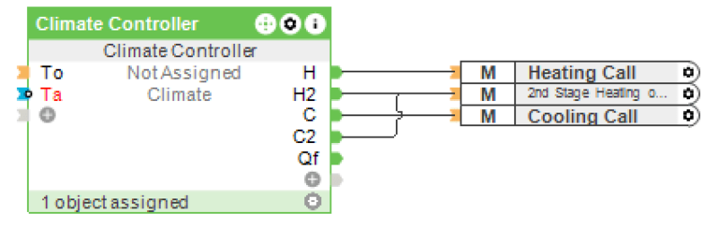
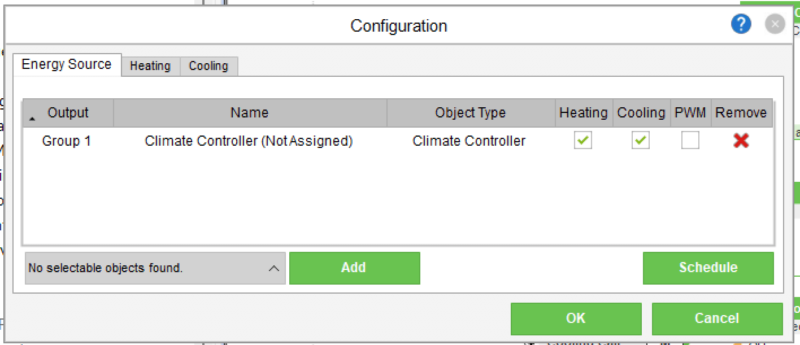
Create a Climate Controller and create three memory flags
- Add a Climate Controller to your page, name, categorise and assign it to the appropriate room/area
- Set the Heating Type parameter to ‘Simple Control’
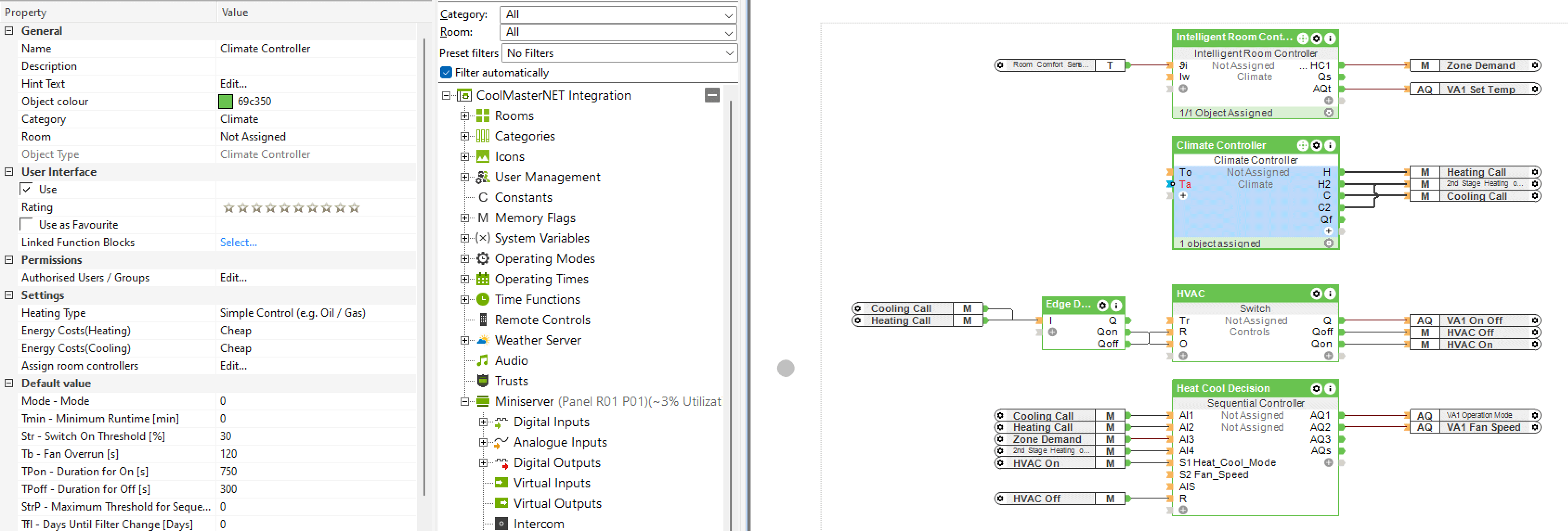
- Create 3 memory flags
-
- Connect one to output H and name it ‘Heating Call’
- Connect one to output C and name it ‘Cooling Call’
- Connect one to both output H2 and C2 and name it ‘2nd Stage Heating and Cooling’
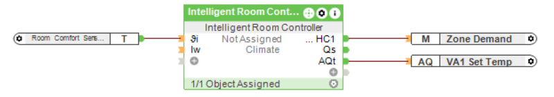
Create and configure an Intelligent Room Controller
- Add an Intelligent Room Controller to your page, ensure it is in the correct category and room.
- Connect your temperature input from your chosen device (see Required Hardware for recommendations)
- Assign the Climate Controller
- Double click the Intelligent Room Controller
- Select the correct Climate Controller from the menu on the bottom left of the window and click add

- Ensure the Heating & Cooling is ticked and then confirm by clicking OK
- Connect ‘Set Temp’ for correct VA (see Creating VA (Virtual Address) list) to output AQt
- Create a memory flag, name it Zone Demand and connect it to output HC1
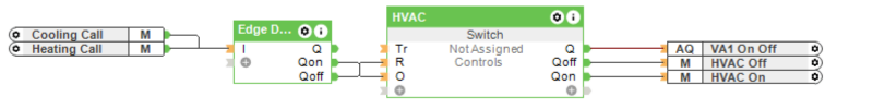
Create a Switch to toggle the on/off state of the Zone
- Add a Switch to your page and name it HVAC
- Add an Edge Detection to your page
- Connect the Qon output from the Edge Detection function block to the O input on the Switch function block
- Connect the Qoff output from the Edge Detection function block to the R input on the Switch function block
- Connect the Heating Call and Cooling Call memory flags we created in Step 3 to the I input of the Edge Detection function block
- Connect the On Off actuator for the correct VA to the Q output of the Switch
- Create a memory flag, name it HVAC On and connect it to the Qon output of the Switch
- Create a memory flag, name it HVAC off and connect it to the Qoff output of the Switch
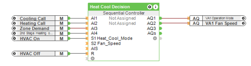
Use the Sequential Controller to determine Operation Mode and Fan Speed
- Add a Sequential Controller to your page and name, categorise and assign it to an appropriate room
- Connect the Cooling Call memory flag to AI1 input
- Connect the Heating Call memory flag to AI2 input
- Connect Zone Demand memory flag to AI3 input
- Connect 2nd Stage Heating and Cooling memory flag to AI4 input
- Connect HVAC On memory flag to S1 input
- Connect HVAC Off memory flag to R input
- Connect Operation Mode actuator for correct VA to AQ1 output
- Connect Fan Speed actuator for correct VA to AQ2 output
Configure sequences within the Sequential Controller for Heat and Cooling decision and Fan speed
- Double click the Sequential Controller to open up the command line editor
- See images for structure and command line both Heating and Cooling decisions and Fan Speed. Ensure that the Heating and Cooling decision is the first sequence and the Fan speed is the second.
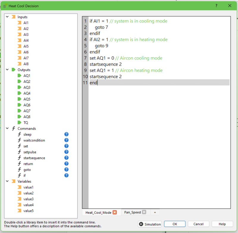
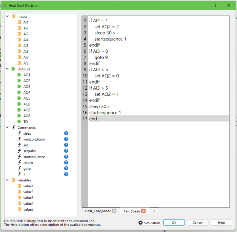
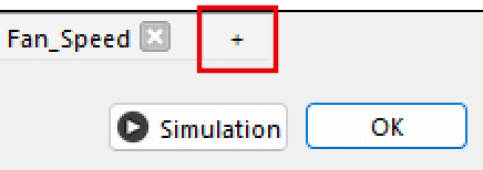
- A second sequence can be added by clicking on the + next to the sequence list at the bottom of the window.
Config Outcome
Your final configuration should look similar to the one shown in the below image for each zone.
