The LOXONE Smart Pool Part 2!
Back in 2013, we published a blog which looked at seven automation features that were implemented in Loxone co-founder Martin’s smart pool. Since the sun has finally started to peek through the clouds, we thought we’d return to Martin’s pool (not literally sadly, despite the promising Austrian weather!) and take a look at Part 2 of the blog.
The first blog looked at the user-facing aspects of the pool. We would definitely recommend reading it before diving into part 2 (pardon the pun). To read it, please click here.
In part two of this blog, we will be focussing on the technical side of the project: which hardware was used and how Loxone Config was programmed. This blog has been translated from Martin’s original German version and written from Martin’s perspective, so over to you, Martin!
Foreword About Standards & Pool Controls
“From my perspective, there are no real standards set out in terms of pool controls and benchmark measurements. There are, however, good orientation guides – not to mention good old-fashioned common sense. Both of these aspects informed all our considerations.
There were many moments when we had hoped for better sensors and a wider range to choose from, especially when it came to water quality.
As a self-confessed newbie in this area, I was amazed that there weren’t any sensors for giving a simple rating of water quality on a scale of 1 to 10.”
The Joyful End Result
“As always, we made the best of the situation and we are enjoying the end result. And I can even make that statement with a clean conscience because the pool has been in use for a few weeks now.
The heart of our pool’s technological elements is, of course, our Loxone Miniserver.
One last piece of additional information before we get going: in this blog I focus on the control technology aspects, without going into detail about the sand filter, sheeting and so on, since these are standard components. The installation of the pool itself was done by Mittermüller GmbH. We (Loxone) designed and implemented the controls as a template to be imitated and copied.
I would like to say a special thank you to the Loxone Support Team in Austria, especially Martin Groiss for his tireless commitment to pursuing perfection in this project (installing -> testing -> modifying -> testing -> etc.)”
Programming
Because the programming was done using an internal developer version of Loxone Config, we cannot currently make this file available for download due to a lack of compatibility.
For this reason, I have included several screenshots. No new features are used, so imitating it using the latest official version won’t be a problem.
Feature 1: Pro Training, Chill-out Swim, Whirlpool
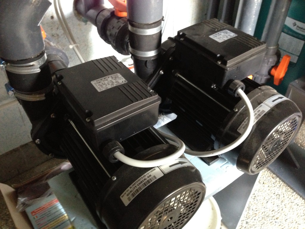
The two pumps that are used here each have an output power of 2.8 kW. That is pretty powerful stuff and you could easily use a less powerful model if you’re not working towards a specific training goal.
The Hardware
To regulate the intensity of the pumps (i.e. the revolutions per minute, rpm), we used Danfoss frequency converters (FCs). VLT Microdrive model (NB: Model should be compatible with pump etc.).
We use this to regulate the RPM of the pump from about 15 to 55 Hz. The FCs have an analogue input, which is fantastic because it means they can be controlled using the analogue output from the Miniserver.
Any pros reading this will know that reducing the frequency can cause a high frequency humming sound. This does happen in our system but the sound is masked by the sound of the water jets, meaning that it cannot be heard and is not a problem.
A Tip For The Piping System
Some advice at this stage: on the recommendation of our swimming pool installers, we placed the intake for the pumps on one side of the pool and the jets on the other side. The result of this is a really great current right through the pool. As I learnt in a conversation last week, this is not necessarily the status quo.
The Software – Loxone Config
The lighting controller function block offered an appropriate template for implementation in Loxone Config.
It has the necessary functions to quickly and easily implement the three scenarios/scenes:
- Pro Training
- Chill-out Swim
- Whirlpool
These can be easily altered using the app, one of the design features of the function block’s interface. The function block also has the necessary input and output channels.
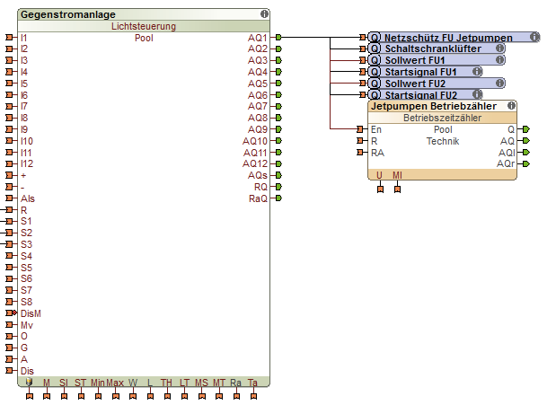
As you can see from the screen shot, the FCs require a start signal as well as a set value. When activated, we also switch on the cooling fan in the distribution box. We also activate the running period timer, essentially a free additional feature that uses the app interface to inform you about the run time of the pumps. This would, for example, make it easy to adhere to the pumps’ recommended maintenance intervals.
The scenarios are then simply stored in the function block as scenes. We introduced the interface for this in part 1.
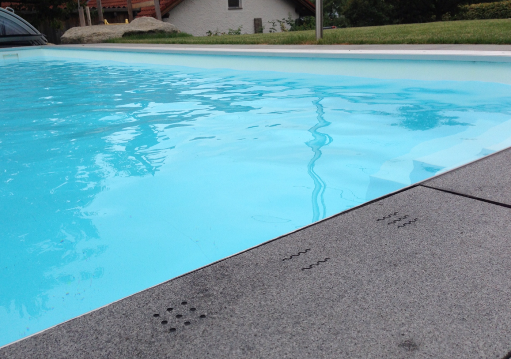
Feature 2: Granite Controls (my personal favourite)
I knew from the word go that I didn’t want any mechanical switches next to the pool. When searching for another solution, we remembered the touch sensors by Edisen, which we once tested for use with something else.
The Hardware
The sensors can be placed behind (almost) any solid surface. They react to changes in the electric field and send a “shut” signal – like a button on a 24V basis. It works on the same principle as a capacitive touch panel.
The exact model we used was the MT0.5-ST. You can find more information about it here.
I expect that this has got the cogs whirring for some of our readers: behind tiles, in furniture, behind fabric… Yes, this kind is a sensor to get the imagination whirring!
There are two things to bear in mind here:
- In our experience, for perfect results, the stone should not be too thick. That meant that the paving slab had to go to the CNC cutting machine for engraving and milling.
- It also reacts if water laps over it, as this also causes a change in the electric field. That’s why we read the sensors after every impulse of electricity that causes a new calibration. It’s a practical trick that makes for perfect results.
The rest was easy: the sensors are wired in the conventional way (to a digital input and electricity supply) and are then stuck to the bottom of the paving stone with silicon.
Unfortunately, I forgot to take a photograph of this. So here’s another photo from above instead:
The Software
In terms of software, the whole thing can be easily implemented and it’s pretty unspectacular:
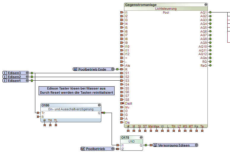
As I mentioned in part 1, this feature is the real highlight and it makes waves with all our visitors (pardon the pun, again). Its popularity with kids does warrant the question of how best it could be made childproof. Perhaps by pressing two of the sensor switches at the same time…
Feature 3: Adjustable Filtration Runs
Now to briefly return to the nitty gritty.
The length of time that the filtration pump runs for is automatically calculated according to the water temperature.
- Filtration runs twice a day with a water temperature of 20° C
- Filtration runs four times a day with a water temperature of 30° C
Read about this in more detail in part 1.
The Hardware
Depending on its performance, we simply switch the filter pump on and off via a digital output using a “contactor”.
NB: We purposefully omitted using the speed regulation on this pump due to the higher-frequency noises that these cause.
Because water temperature is the only factor we are using to determine the duration, the only sensor we need is a simple 1-Wire temperature probe or contact sensor. When attached to our 1-Wire Extension, this will deliver precise values.
Location, location, location
An important note: you will only get a good reading if the sensor is placed in a good location and if the water has been freshly mixed (e.g. during filtration). We installed two sensors (one after the skimmer inlet and another right next to the intake for the jet pumps) and, after making careful observations, we then decided on one.
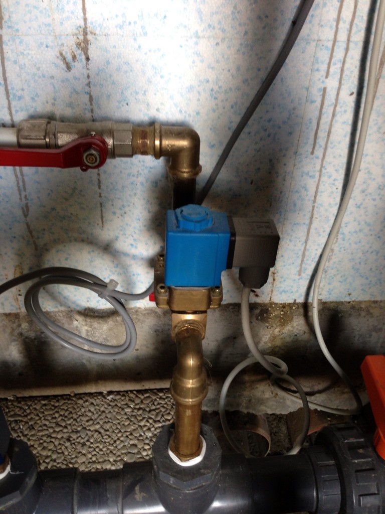
To achieve the highest level of automatisation, we recommend adding a motorised 6-way valve – these are usually operated manually. We used a product by Peraqua ((MP-6 design, 24V DC, 1 1/2″). It moves itself into the desired position according to digital inputs.
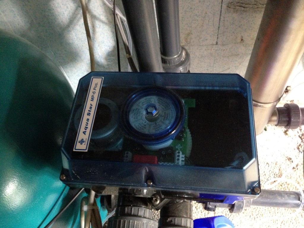
When the valve is in position, we receive notification via a “confirmation result”. Depending on the position that is required, this can take 15 seconds or longer.
NB: Water loss may occur when the valve is moving into position. That’s why we set up the whole configuration to require as few valve movements as possible.
The Software
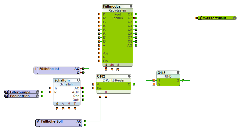
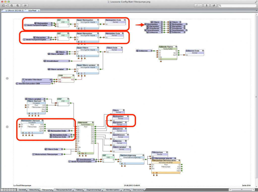
The duration is calculated in a dedicated page in Loxone Config:
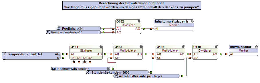
Two important parameters in this calculation are the pool’s water content (in m3) and the time that the pump requires to filter the contents of the whole pool once through.
WARNING: The following screen shot may look complicated (German aside!) but it aims to aid understanding, showing an overview of the configuration of all the filter pumps. The sections relevant for this feature are highlighted.
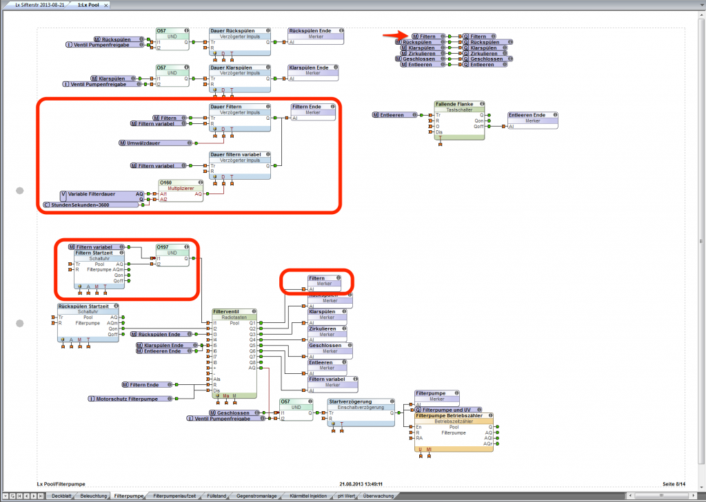
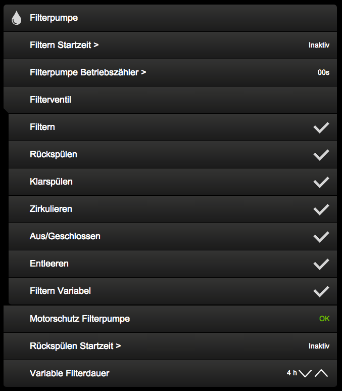
The radio button function block visible on the screen results in the following interface (sorry about the German again, you’ll have to be imaginative here!):
The “memory flags” pass on the status of the output from the radio buttons to the appropriate logic. This has numerous advantages, including a clearly arranged configuration.
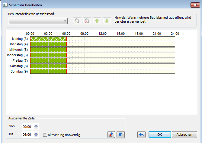
The desired start times for the filtration process are stored in the settings for the time switch function block.
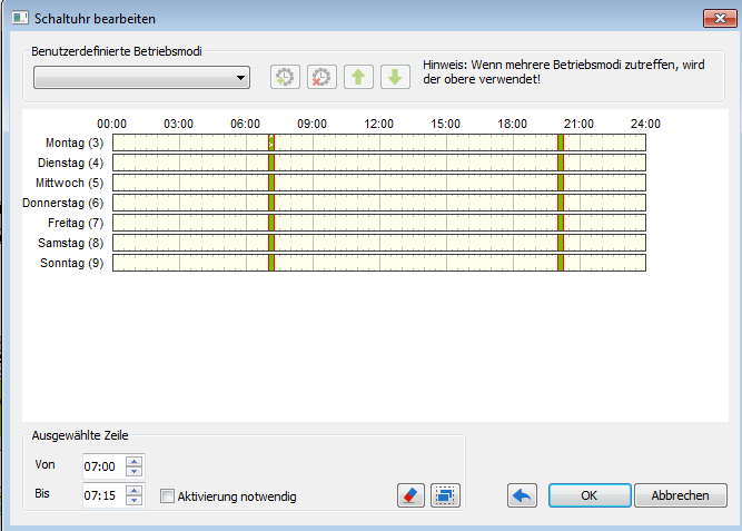
These can, of course, be quickly and easily changed at any time in the app.
Feature 4: Automatic Top-Up
Every night, we refill the pool to our chosen level.
The Hardware
There are various options for measuring the pool’s water level. We decided on a pressure sensor, which sends an analogue signal from 0-10V which, once calibration has taken place, reflects the water level of the pool.
NB: If a pump is running or someone is in the pool, this alters the pressure and thus the measured value. That means that measuring and topping up can only happen during periods of “inactivity”.
Being completely honest: The sensor that we installed does not have the optimum measurement range and so the results are somewhat mediocre. That’s why I’m not offering information about hardware
However, our buying department is working hard to find an appropriate sensor. When it’s been found, it will be available in our shop.
We also integrated a standard solenoid valve into the water supply.
The Software
In terms of software, the implementation looks like this:
The desired time period for top-up is stored in the time switch. In our case, it is between midnight and 6am.
We work on the assumption that at some point during this period no pumps will be running and that the pool will not be in use. (This will be checked via the sensors in the pool cover – more on this later!)
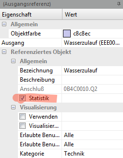
To get an idea of how often we had to let more water in, we use the Loxone Config integrated statistics feature. Simply tick the option – easy as that!
Feature 5: Fully Integrated Lighting
Having now used the pool a lot for several weeks, I can tell you from experience that we have never had to manually switch on the lights. They switch on and off automatically when it starts to get dark and when there is activity on the terrace. This is integrated into the rest of the ambient lighting in the garden. There is a post about this already, in case you’re interested.
The Hardware
We want our pool to have a splash of colour, which led us to choose coloured LED spotlights. There can be controlled using DMX, making them perfect for our DMX Extension.
Our swimming pool builders, the Mittermüller family, recommended the following product to us: Lumiplus PAR65 DMX by Astralpool.
The Software
The software implementation is fairly straightforward: I use the lighting controller function block, which means I can intervene manually using the app.
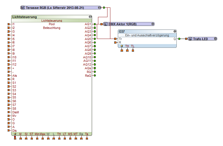
I use a memory flag to get the RGB value of the “remaining” ambient lighting and then I simply use these values directly.
To save electricity, I only switch on the transformer for the spotlights if necessary. When the lighting switches off, it doesn’t abruptly plunge us into darkness, it gently fades out. The switch-off delay visible in the screen shot prevents the transformer from switching off the light too quickly.
Feature 6: Pool Cover Monitoring and Alarm
As mentioned in part 1, monitoring the pool cover was very important to us. As there was no ready-to-use solution, we took the task on ourselves.
The Hardware
We installed standard reed switches in the dome cover. The Miniserver and/or the Extension analyse these using digital inputs.
The Software
We use the alarm system function block as a basis. This is easy to use and has the perfect interface for our requirements.

If the alarm system is activated, opening a segment will immediately set off the alarm. For us, that immediately triggers, amongst other things, the integrated Caller Service.
Five minutes after the pool cover is closed (“finished using pool” memory flag), the alarm system is re-activated. It is also automatically activated at midnight.
Alongside the app, double clicking on the up/down switch on the “Poolbank” will deactivate the alarm system. This is a normal rocker switch.
Feature 7: Care Free – Automatic Filter Cleaning
For this feature, both your filter pump and your 6-way valve must be automated. I mentioned this already as part of Feature 3.
Its implementation is inspired by the automatic filtration – it just has different valve settings.
The Software
I have again highlighted the relevant parts in the following screen shot.
I put the desired time into the timer. Because we have covered this a few times already in this blog, I won’t bother including a screen shot here. 😉
In this process, we first use the function for backflushing the filter, followed by a clear-flush. These are both settings on the 6-way valve that we request one after the other. The duration of each of the two processes is stored in the delayed pulse function block. If we wanted to, we could have this show up in the app as well but we made a conscious decision not to.
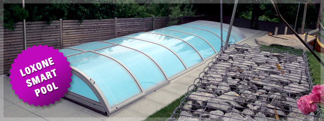
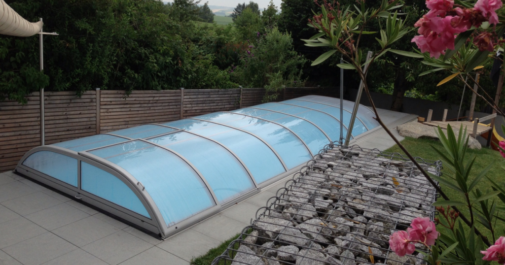
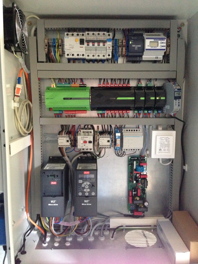
Conclusion: Enclosure and Diagram
I would like to conclude with a photo of the enclosure:
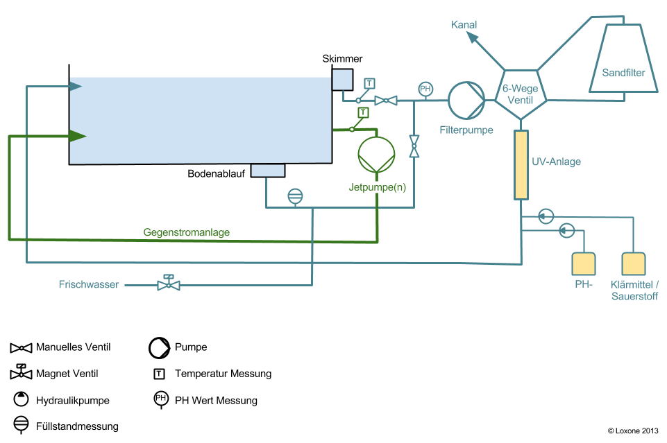
As well as a technical diagram that was created while the work was being done.
Summary
I hope this blog has provided a good overview regarding the available options and the implementation.
The wide array of pool technology currently available (from pumps to various controls) makes it impossible to create a failsafe, thorough implementation guide. Unfortunately, it remains the case that Smart Pools are individual projects that require a certain level of skill and know-how.