This block controls fan coil units, typically used in commercial buildings and hotels.
Based on the current room temperature (ϑc) and target temperature (ϑt), the air volume is regulated via a PI controller.
The heating and cooling valves are controlled based on the demand.
Spis treści
Wejścia↑
| Skrót | Krótki opis | Opis | Jednostka | Zakres wartości |
|---|---|---|---|---|
| ϑc | Current Room Temperature | Funkcję tę zapewni podłączony Inteligentny regulator pomieszczeniowy | ° | ∞ |
| ϑt | Target Room Temperature | Funkcję tę zapewni podłączony Inteligentny regulator pomieszczeniowy | ° | ∞ |
| Ha | Heating Available | Określa, czy źródło ogrzewania jest dostępne. Wartość PRAWDA oznacza, że nie jest podłączone. | - | 0/1 |
| Ca | Cooling Available | Określa, czy źródło chłodzenia jest dostępne. Wartość PRAWDA oznacza brak połączenia. | - | 0/1 |
| Dwc | Door and Window Contact | 0 = Zamknięte 1 = Otwarte | - | 0/1 |
| Rtd | Reset to default | Resetuje parametry i ustawienia bloku do wartości domyślnych określonych w ustawieniu wstępnym bloku. | - | 0/1 |
| Off | Off | Pulse: Wyłącza wentylator i zawory. On: Wyłącza wszystkie wyjścia, resetuje liczniki czasu i blokuje blok. Wejście dominujące. | - | 0/1 |
| Sm | Silent Mode | Po włączeniu maksymalna prędkość wentylatora zostanie ustawiona zgodnie z ustawieniem "Prędkość wentylatora w trybie cichym". Po ponownym wyłączeniu prędkość wentylatora zostanie ponownie obliczona. | - | 0/1 |
| Bm | Boost Mode | Ustawia prędkość wentylatora na maksymalną. | - | 0/1 |
| Pt | Pause Timer | Wstrzymuje urządzenie na czas ustawiony w parametrze (Ptd). | - | 0/1 |
| Fan | Fan Speed | Prędkość wentylatora wyrażona jako procent pełnej mocy. -1 w trybie automatycznym. -1, jeśli nie jest podłączony. | % | -1...100 |
Parametry↑
| Skrót | Krótki opis | Opis | Jednostka | Zakres wartości | Wartość standardowa |
|---|---|---|---|---|---|
| Fmax | Maximum Fan Speed in Auto Mode | Maksymalna prędkość wentylatora w trybie automatycznym | % | 0...100 | 80 |
| Mode | Mode | 0 = Wyłączone 1 = Automatycznie 2 = Ogrzewanie 3 = Chłodzenie 4 = Wentylacja W przypadku ustawienia opcji „Automatycznie” i sterowania za pomocą regulatora pomieszczeniowego, ustawienie zostanie określone przez IRC | - | 0...4 | 1 |
| Ptd | Pause Timer Duration | Rozpoczyna się wraz z narastającym zboczem sygnału wejściowego (Pt). Urządzenie pozostaje w stanie wstrzymania przez określony czas. | s | 0...∞ | 7200 |
| FϑKP | Proportional Gain (Fan) | Współczynnik wzmocnienia proporcjonalnego dla mocy wentylatora w zależności od temperatury. Stosowany w regulatorze PI. | - | 0...∞ | 50 |
| FϑKI | Integral Gain (Fan) | Współczynnik wzmocnienia integralnego dla mocy wentylatora w zależności od temperatury. Stosowany w regulatorze PI. | - | 0...∞ | 0.01 |
| FϑSt | Sample Time (Fan) | Czas próbkowania dla sygnału wyjściowego wentylatora w zależności od temperatury. Stosowany w regulatorze PI. | s | 0...∞ | 60 |
Wyjścia↑
| Skrót | Krótki opis | Opis | Jednostka | Zakres wartości |
|---|---|---|---|---|
| H | Heating Output | Wyjście ogrzewania | - | 0...10 |
| C | Cooling Output | Wyjście chłodzenia | - | 0...10 |
| HC | Combined Heating/Cooling Output | Wyjście dla zaworów lub siłowników, które mogą ogrzewać i chłodzić | - | 0...10 |
| Fan | Fan Speed Analogue | Analogowa regulacja prędkości wentylatora | - | 0...100 |
| FanS | Fan Speed Step | Aktualny stopień obrotów obliczono na podstawie ustawienia "Stopnie prędkości wentylatora”. | - | 0...∞ |
| ϑc | Current Room Temperature | Aktualna temperatura w pomieszczeniu | ° | ∞ |
| ϑt | Target Room Temperature | Docelowa temperatura w pomieszczeniu | ° | ∞ |
| Mode | Current Mode | 0 = Wyłączone 1 = Automatycznie 2 = Ogrzewanie 3 = Chłodzenie 4 = Wentylacja | - | 0...4 |
| S | Status | Aktywne, gdy którykolwiek z zaworów jest otwarty lub gdy wentylator pracuje. | - | 0/1 |
| API | API Connector | Inteligentne złącze oparte na API. API Commands | - | - |
Właściwości↑
| Krótki opis | Opis | Jednostka | Zakres wartości | Wartość standardowa |
|---|---|---|---|---|
| Stopnie prędkości wentylatora | Do mapowania poszczególnych kroków. Przykład: 4 kroki -> 25% pełnej mocy dla każdego kroku | - | 0...100 | 3 |
| Prędkość wentylatora w trybie cichym | Maksymalna prędkość wentylatora w trybie cichym | % | 0...100 | 10 |
Functional Description↑
This block regulates the air volume as well as heating and cooling output based on the current temperature and target temperature.
The air volume is only increased as necessary to maintain the target temperature, since higher air volumes lead to higher energy losses.
The outputs are controlled according to the following operating logic:
| Operating Mode | Air Volume | Heating Output | Cooling Output |
|---|---|---|---|
| Heating | ϑ variable | 100 % | Everything Ok |
| Cooling | ϑ variable | Everything Ok | 100 % |
| Everything Ok | Everything Ok | Everything Ok | Everything Ok |
ϑ variable
The air volume is adjusted depending on the difference between current temperature and target temperature.
The heating or cooling output operates at full capacity.
 | To ensure stable and non‑disruptive control, the air volume is adjusted once per minute, with changes limited to a maximum of 20%. As a result, a full adjustment from 100% to 0% requires five minutes. |
Programming Example↑
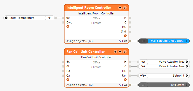
Combination with Intelligent Room Controller
The heating and cooling valves as well as the fan are connected to the corresponding outputs of the block.
The Fan Coil Unit Controller can be connected to the Intelligent Room Controller via the API Connector:
In the properties window, the PI controller parameters for the temperature-based fan regulation can be adjusted:
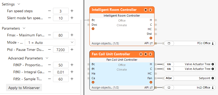
Since this example uses a 4-pipe system, the inputs (Ha) and (Ca) do not need to be connected, as heating and cooling are assumed to be available by default.
The Intelligent Room Controller handles the room logic and passes temperature values and heating/cooling requirements to the Fan Coil Unit Controller.
This adjusts the air volume and heating/cooling valves.
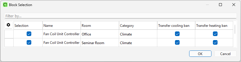
Combination with Intelligent Room Controller and Fan Coil Central Controller
By double-clicking the central block, the corresponding Fan Coil Unit Controllers can be added:
In the properties window, the system type (2-pipe or 4-pipe) can be selected directly:
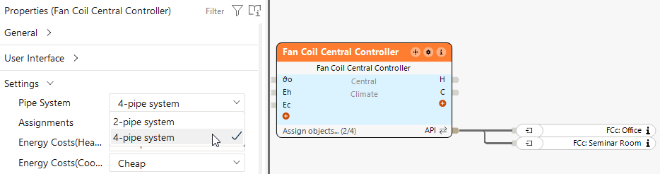
The Fan Coil Central Controller gathers the demands and decides between heating and cooling.
Based on this decision, the Fan Coil Unit Controllers adjust the valves and air volume in the respective rooms.
This block can also operate standalone. In this case, temperature values are passed directly to the block via the inputs..