The 1-wire Extension allows the integration of 1-wire sensors like temperature sensors, or iButtons for access control.
Table of Contents
- Commissioning
- Connecting 1-wire sensors
- Pairing 1-wire sensors
- Polling cycle
- iButton Access Control
- Troubleshooting
- Supported sensors
- Inputs, Outputs, Properties
- Safety Instructions
- Documents
Commissioning↑
The 1-wire Extension is installed on a DIN rail in a suitable enclosure.
Connect the power supply and Link communication to the Miniserver.
The 1-wire sensors are connected to the 1-wire interfaces. Please follow the detailed instructions for connecting sensors below.
The Extension starts after switching on the power supply, and the status LED will flash orange after a short time when the connection to the Miniserver is established.
Then follow the pairing procedure on the Link Interface.
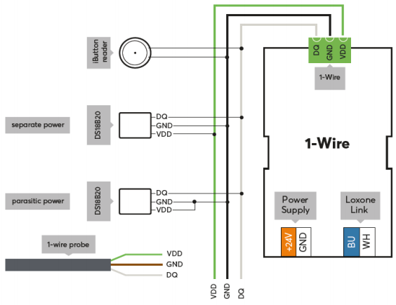
Connecting 1-wire sensors↑
We recommend connecting no more than 20 sensors or one iButton reader to the 1-wire bus.
Up to 32 sensors are possible, but wiring requirements will increase and the possible cable length and polling cycle will decrease.
Use a twisted pair of a shielded CAT5/6/7 cable for the signal lines DQ and GND. VDD can be connected to another conductor of the CAT cable.
The shield of the cable must not be connected, and no other data signals should be transmitted in the same cable.
The maximum length of the 1-wire bus depends on the wiring topology. For linear topology and bus topology with short taps up to 300m, for bus topology with long taps and star topology up to 100m. If sensors are connected parasitically, the total length is also limited to 100m.
Many 1-wire sensors support parasitic power supply, where the sensor is supplied via the data line DQ. The sensor's VDD is connected to GND. This way one conductor can be saved at the expense of the maximum length of the 1-wire bus. Also, their temperature measuring range is limited to a maximum of +85°C in this case.
Pairing 1-wire sensors↑
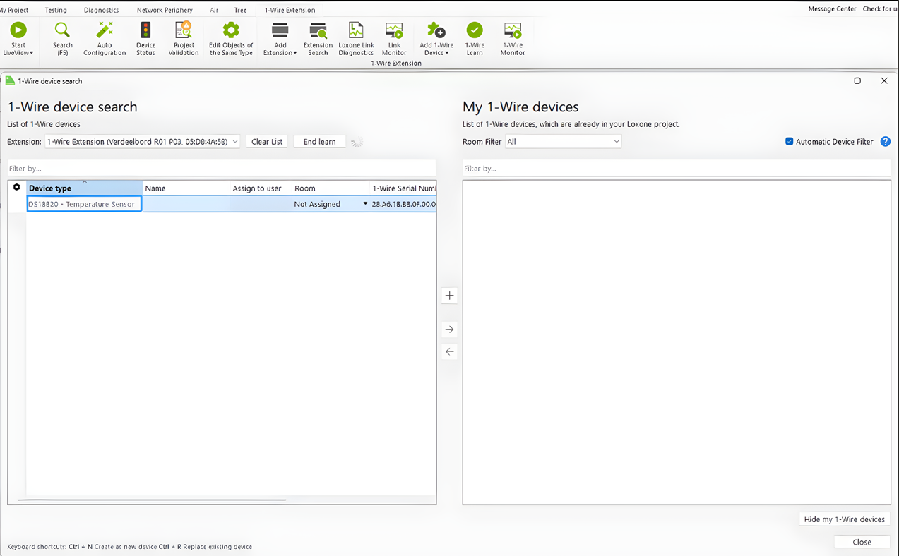
1. Select the 1-Wire Extension in Loxone Config.
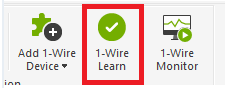
2. Click on 1-Wire Learn.
The 1-Wire Extension will then search for connected devices and display all detected 1-Wire sensors.
Now select the sensor, enter a name, and then click on +.
There are several ways to identify the sensors. The 1-wire Temperature Probes that are available from Loxone have a label with a printed serial number that can be used to identify the sensor. You can also connect only one sensor at a time and always pair the newest one. Another option is to first pair all sensors and temporarily set the polling cycle of the sensors to one second. Then the sensor can be identified by simply touching it based on the temperature change.
To apply the changes, save the program in the Miniserver.
Now the added sensors are ready for use and available in Loxone Config.
Polling cycle↑
The polling cycle can be set for each sensor. For most applications a value of 60 seconds is recommended. Depending on the number of sensors, however, it is not possible to set a short polling cycle for each sensor.
For applications with slow temperature changes (e.g. room temperature), the scanning cycle can also be set to e.g. 300 seconds. For applications such as the control of a flow temperature, a polling cycle of 5 seconds may be necessary.
In general, therefore, the polling cycle of a sensor should only be set as short as necessary. Shorter polling cycles can be achieved with fewer sensors.
iButton Access Control↑
iButtons provide an access control solution. An iButton reader is connected to the 1-wire Extension. For each access point (main entrance, door, garage) one 1-wire Extension and one key reader is required. The iButtons are also 1-wire sensors with a unique serial number. Any number of iButtons can be paired and assigned to different users. Thus the iButton becomes the key.
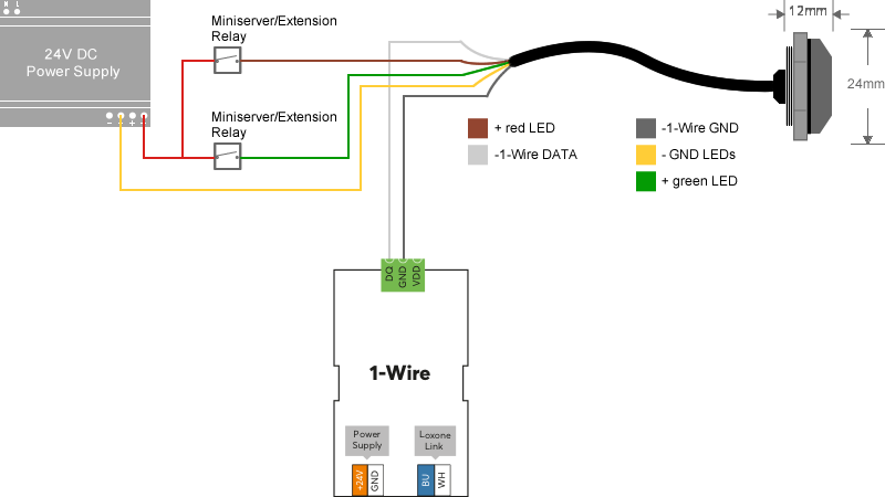
The iButton key reader is connected to the 1-wire Extension via GND and DQ, but it also contains a red and a green LED that can be controlled separately. Key readers purchased from Loxone since 2015 have an integrated resistor that allows the LEDs to be powered directly by 24VDC. Connect the key reader according to the following diagram:
To pair iButtons, first select the 1-wire Extension in Loxone Config, and then click on 1-Wire Learn.
Then briefly place the iButton on the key reader several times, so that it is displayed in the 1-wire learning window:
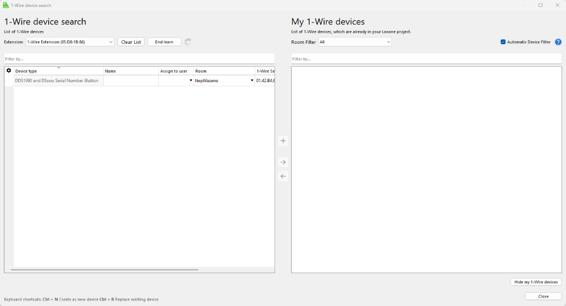
Now select the desired iButton, choose a user from the drop-down list in properties and click on + icon You can also not assign the user to create a digital input.
To apply the changes, save the program in the Miniserver.
Several iButton readers on a 1-wire Extension
If several iButton readers are connected to a 1-wire Extension, it is not possible for the 1-wire Extension to detect at which reader the iButton was held on. In this case, an additional contact per iButton reader is necessary to identify the iButton reader used in order to open the correct door. Therefore, we generally recommend a 1-wire extension per iButton reader.
Troubleshooting↑
If sensors are not or only partially found, or provide invalid values, it is often due to incorrect wiring.
It is helpful to know the wiring of the installation well.
Using e.g. the Device Status, check whether only sensors in a certain room, or sensors beyond a certain point in the wiring are affected.
The voltage on the 1-wire bus can be measured at the various terminal connections. Between VDD and GND the voltage is always 5VDC. DQ carries a clocked signal, usually the measurements between DQ and GND fluctuate between 1-5VDC, depending on data traffic. These voltages must be present at each sensor.
This will help localize and identify possible causes such as faulty connections or reversed data lines.
On an iButton reader, the central contact area is connected to DQ and the outer ring is connected to GND. The voltage can also be measured here.
Frequency converters can interfere with 1-wire communication under unfavorable conditions. If this occurs, install frequency converters and wiring separately from 1-wire devices.
Supported sensors↑
The 1-Wire Sealed Sensor can be used universally for heating/ventilation/air conditioning.
It is typically used with an immersion sleeves or attached directly to a pipe.
The 1-Wire Temperature Sensor Set contains compact sensors, which can be placed e.g. in a wall box behind a switch or in another housing.
Concealed mounting results in a delay in the detection of the temperature, which is usually tolerable in applications such as the control of room temperature.
It is important to seal the conduits to the wall box in order to prevent incorrect measurements due to draft air.
| Sensor type (Family Code) | Description |
|---|---|
| DS1822 (22) | Temperature sensor |
| DS18B20 (28) | Temperature sensor |
| DS18S20 (10) | Temperature sensor |
| DS1963S (18) | iButton |
| DS1990 (01) | iButton |
| DS2438 (26) | Smart Battery Monitor |
All 1-wire Extensions produced since 2015 periodically reset the power supply of the 1-wire bus to prevent measured values from freezing. These short power supply interruptions can cause issues with sensors containing microcontrollers. These sensors should be supplied with a separate 5V power supply.
Diagnostic Inputs↑
| Summary | Description | Unit | Value Range |
|---|---|---|---|
| Online Status 1-Wire Extension | Indicates whether the device can be reached by the Miniserver. Diagnostics for Air devices Diagnostics for Tree devices Diagnostics for Extensions | Digital | 0/1 |
Properties↑
| Summary | Description | Default Value |
|---|---|---|
| Serial Number | Specifies the serial number of the device. Enter 'Auto' to automatically pair an Extension with unknown serial number. This can only be used if there is only one Extension of the same type on a standalone Miniserver (not in a Client-Gateway setup). Save in the Miniserver to pair the Extension. Afterwards the program must be loaded from the Miniserver to transfer the actual serial number of the Extension into the program. | - |
| Monitor Online Status | If checked, you will be notified via System Status or the Mailer if the device is no longer available or goes offline. | - |
Safety Instructions↑
Installation must be carried out by a qualified electrician in accordance with the applicable regulations.
This device must be mounted on a DIN rail in an electrical distribution enclosure to ensure protection against contact, water and dust.
Documents↑
Datasheet 1-wire Temperature Probe