Your Space, Perfectly Orchestrated.

It Just Works.
Lighting adapts. Climate adjusts. Energy flows where it’s needed. Automatically. Effortlessly.

One System.
Everything works together. No juggling apps. No separate systems to manage.

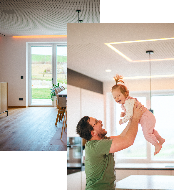
Built Around You.
An apartment, a house or a workplace – LOXONE fits your space and your life.
We’ve Got the Whole Building Covered.
All vital building functions – automated, connected and quietly running in the background.


Lighting
Not just lights, lighting that gets the moment. It knows when it’s sunrise, movie time, or when your hands are full, so light becomes part of life, not another task.
Learn more


Shading
Blinds that know when you need a little vitamin D and when you need a little privacy. They move automatically for shade, light, or a little peace and quiet – no pulling strings, no guessing.
Learn more


Audio
Sound becomes a natural part of the space. Welcoming, guiding, or simply playing in the background. Always in the right place, at the right time, without anyone needing to manage it.
Learn more

Energy
Lights off when no one’s around. Heating down when the sun’s already putting in the effort. Loxone quietly cuts waste in the background, lowering bills without lowering comfort.
Learn more


Climate
Warm when it should be. Fresh when it matters. LOXONE keeps every room in balance with what’s happening inside and outside – so no one has to touch a thing.
Learn more


Access
Let someone in, lock up remotely, or see who dropped by – with your phone, a code, or a tap. No keys, no compromise.
Learn more


Security
Doors locked, windows checked, movements covered. Your building stays protected without feeling controlled. Always aware. Always ready. Only stepping in when it really matters.
Learn more
Built for Everyone.
Homeowners
Business Owners
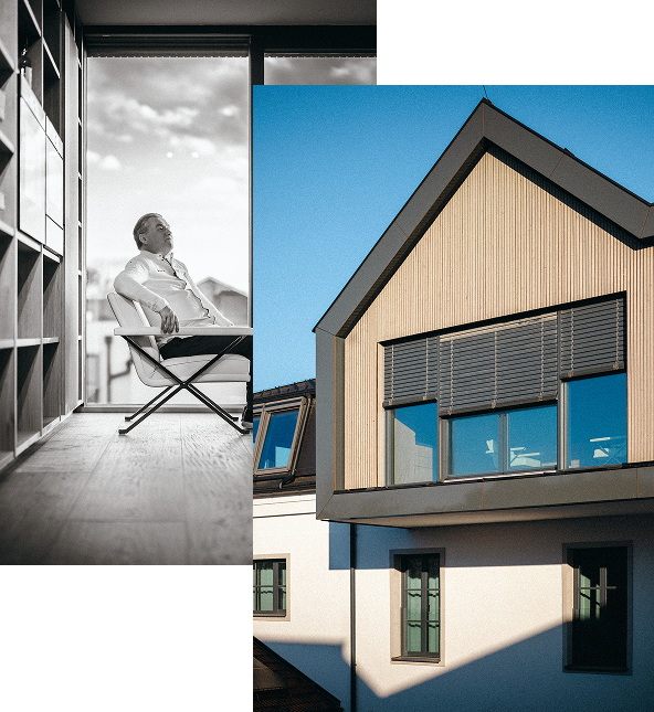
Architects
MEPs
Installers
Your Path to LOXONE
Make the Most of Your Space
You want a building that thinks ahead.
One that takes work off your plate instead of adding more.
Start Your Journey as a Partner
You’re looking for a solution that inspires your customers.
A solution that opens new opportunities for you and your business.

It’s Easier Than You Think
Step 1
Discover what’s possible
LOXONE is about how you live, not technology.
How do you want to live, work and feel in your space?
Get a clear idea of what your building can do for you.
Step 2
Plan together
A LOXONE Partner guides you from the very beginning.
Everything is planned as one system, designed to work seamlessly.
The result is a solution that just works from day one.
Step 3
Live smart
Lighting, climate, shading, audio, security and energy all work together.
Everything adapts to the organic flow of your daily life.
Find a LOXONE Partner

It’s Easier Than You Think
Step 1
Discover how it all works together
Learn how to deliver smart automation with Foundation Training.
Everything connects seamlessly – from planning to implementation.
That simplicity stays with you in every project.
Implement with ease
Less effort during installation and commissioning.
More time for your customers.
Grow together
You build on a system that proves itself in every project.
From homes to large-scale commercial buildings, it grows with you.
Just like your business.
Become a LOXONE Partner
Highlights

LOXONE App 17.1
Discover what new in our latest app update.
Wireless Speaker
Full sound anywhere without wiring.
Config and App 17
Fresh Design and New Features
Exosphere
Improved Analysis and Easier Navigation
AC Control Air for Panasonic
Smart air conditioning.
Touch Pure
Even more intuitive thanks to a new design.
Built for Buildings.
Loved by People.
“I love how easy our smart home makes everyday life – everything is controlled in one place, whether it’s lighting, music, or shading. Even when I’m away, I always feel in control. What really stands out to me is the energy management – PV, EV, and the home all perfectly in sync. And still, everything stays incredibly simple to use.”
Otmar Martl
Smart Home Owner
“My favorite feature in the new Gutshof is that, with LOXONE, I can define the perfect lighting and the ideal sound for each of the 100 rooms – anytime.”
Toni Mörwald
Chef, Entrepreneur & Cookbook Author
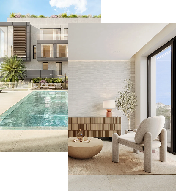
“Over the years, LOXONE has become a strong partner for us, starting with our first two projects here in Mallorca. Today, we can’t imagine developing our properties without it. We’re also seeing how much is evolving in this space – with new products constantly being integrated. What matters most to us is that the systems we install today can still grow and adapt in the future.”
Chris Bauer
Founder XOJAY
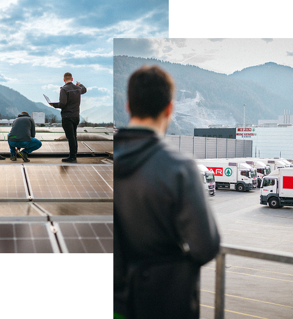
“With LOXONE, we’ve found a partner that makes it easy to bring all external trades together in one system – quickly, simply, and with full flexibility.”
Gerald Geiger
Head of Construction, Energy & Technology, SPAR