This block controls fan coil units with fresh air supply, commonly used in commercial buildings and hotels.
Depending on the current room temperature (ϑc), target temperature (ϑt), and CO2 level (CO2), the air volume and valves are regulated.
The regulation depends on the operating state and is controlled via a PI controller based on temperature or air quality.
Contenido
Entradas↑
| Abreviatura | Resumen | Descripción | Unidad | Rango de valores |
|---|---|---|---|---|
| ϑc | Current Room Temperature | El valor será proporcionado por el Controlador de Habitación conectado | ° | ∞ |
| ϑt | Target Room Temperature | El valor será proporcionado por el Controlador de Habitación conectado | ° | ∞ |
| Ha | Heating Available | Especifica si la fuente de calefacción está disponible. VERDADERO si no está conectada. | - | 0/1 |
| Ca | Cooling Available | Especifica si la fuente de refrigeración está disponible. VERDADERO si no está conectada. | - | 0/1 |
| CO2 | Current Room CO2 | Si un Controlador de Habitación está conectado al Controlador de FanCoil con Renovación de Aire y el CO2 está conectado a la entrada, el sistema utiliza el valor de CO2 del Controlador de Habitación e ignora el valor en la entrada (CO2) del Controlador de FanCoil con Renovación de Aire. | ppm | 0...∞ |
| Dwc | Door and Window Contact | 0 = Cerrado 1 = Abierto | - | 0/1 |
| Rtd | Reset to default | Restablece los parámetros y la configuración del bloque de función a los valores por defecto guardados en una plantilla. ¡Esta funcionalidad solo es posible cuando se usa una plantilla! | - | 0/1 |
| Off | Off | Pulso: Apaga el ventilador y las válvulas. Encendido: Todos los salidas se apagan, reinicia los temporizadores y bloquea el módulo. Entrada dominante. | - | 0/1 |
| Sm | Silent Mode | Cuando se activa, la velocidad máxima del ventilador se establece de acuerdo con la configuración de "Velocidad del Ventilador en Modo Silencioso". Cuando se desactiva nuevamente, la velocidad del ventilador se recalculará. | - | 0/1 |
| Bm | Boost Mode | Establece la velocidad del ventilador al máximo. | - | 0/1 |
| Pt | Pause Timer | Pone en pausa el dispositivo durante el tiempo establecido en el parámetro (Ptd). | - | 0/1 |
| Fan | Fan Speed | Velocidad del ventilador en porcentaje de la potencia total. -1 para automático. -1 si no está conectado. | % | -1...100 |
Parámetros↑
| Abreviatura | Resumen | Descripción | Unidad | Rango de valores | Valor por defecto |
|---|---|---|---|---|---|
| CO2t | Target CO2 | Cuando la concentración de CO2 en la habitación supere este valor, comenzará la ventilación. | ppm | 0...∞ | 600 |
| Fmax | Maximum Fan Speed in Auto Mode | Velocidad máxima del ventilador en modo automático | % | 0...100 | 80 |
| Mode | Mode | 0 = Apagado 1 = Automático 2 = Calefacción 3 = Refrigeración 4 = Ventilación Si se configura en Automático y se controla por IRC, será ajustado por el IRC | - | 0...4 | 1 |
| Ptd | Pause Timer Duration | Comienza con el flanco ascendente de la entrada (Pt). Mantiene el dispositivo en pausa durante la duración especificada. | s | 0...∞ | 7200 |
| FϑKP | Proportional Gain (Fan Temp) | Ganancia proporcional para la salida del ventilador basada en la temperatura. Utilizada para el controlador PI. | - | 0...∞ | 50 |
| FϑKI | Integral Gain (Fan Temp) | Ganancia integral para la salida del ventilador basada en la temperatura. Utilizada para el controlador PI. | - | 0...∞ | 0.01 |
| FϑSt | Sample Time (Fan Temp) | Tiempo de muestreo para la salida del ventilador en función de la temperatura. Utilizado para el controlador PI. | s | 0...∞ | 60 |
| Fco2KP | Proportional Gain (Fan CO2) | Ganancia proporcional para la salida del ventilador basada en la calidad del aire (CO2). Utilizada para el controlador PI. | - | 0...∞ | 50 |
| Fco2KI | Integral Gain (Fan CO2) | Ganancia integral para la salida del ventilador basada en la calidad del aire (CO2). Utilizada para el controlador PI. | - | 0...∞ | 0.01 |
| Fco2St | Sample Time (Fan CO2) | Tiempo de muestra para la salida del ventilador basado en la calidad del aire (CO2). Utilizado para el controlador PI. | s | 0...∞ | 60 |
| VKP | Proportional Gain (Valve) | Ganancia proporcional para salidas de válvulas basada en temperatura. Utilizada para controlador PI. | - | 0...∞ | 50 |
| VKI | Integral Gain (Valve) | Ganancia integral para salidas de válvula basada en temperatura. Utilizada para controlador PI. | - | 0...∞ | 0.01 |
| VSt | Sample Time (Valve) | Tiempo de muestreo para salidas de válvulas basado en la temperatura. Utilizado para controlador PI. | s | 0...∞ | 60 |
Salidas↑
| Abreviatura | Resumen | Descripción | Unidad | Rango de valores |
|---|---|---|---|---|
| H | Heating Output | Salida de Calefacción | - | 0...10 |
| C | Cooling Output | Salida de Refrigeración | - | 0...10 |
| HC | Combined Heating/Cooling Output | Salida combinada de calefacción/refrigeración | - | 0...10 |
| Fan | Fan Speed Analogue | Velocidad del ventilador analógica | - | 0...100 |
| FanS | Fan Speed Step | Paso actual calculado con la configuración de "Pasos de Velocidad del Ventilador". | - | 0...∞ |
| ϑc | Current Room Temperature | Temperatura ambiente actual | ° | ∞ |
| ϑt | Target Room Temperature | Temperatura de consigna | ° | ∞ |
| Mode | Current Mode | 0 = Apagado 1 = Automático 2 = Calefacción 3 = Refrigeración 4 = Ventilación | - | 0...4 |
| S | Status | Encendido cuando alguna válvula esté abierta o el ventilador esté activo. | - | 0/1 |
| API | API Connector | Conector inteligente basado en comandos API. | - | - |
Propiedades↑
| Resumen | Descripción | Unidad | Rango de valores | Valor por defecto |
|---|---|---|---|---|
| Pasos de velocidad del ventilador | Para mapear pasos discretos. Ejemplo: 4 pasos -> 25% de la potencia total para cada paso | - | 0...100 | 3 |
| Velocidad del ventilador en modo silencioso | Velocidad máxima del ventilador en modo silencioso | % | 0...100 | 10 |
Functional Description↑
This block regulates air volume as well as heating and cooling output based on current temperature, target temperature, and air quality (CO2).
Humidity is not considered.
The air volume is only increased as necessary to maintain the target temperature and air quality, as larger air volumes lead to higher energy losses.
The outputs are controlled according to the following operating logic:
| Operating Mode | Air Volume | Heating Output | Cooling Output |
|---|---|---|---|
| Heating & Good Air Quality | ϑ variable | 100 % | Everything Ok |
| Heating & Bad Air Quality | CO2 variable | ϑ variable | Everything Ok |
| Cooling & Good Air Quality | ϑ variable | Everything Ok | 100 % |
| Cooling & Bad Air Quality | CO2 variable | Everything Ok | ϑ variable |
| Bad Air Quality | CO2 variable | Everything Ok | Everything Ok |
| Everything Ok | Everything Ok | Everything Ok | Everything Ok |
ϑ variable
The air volume is adjusted depending on the difference between current temperature and target temperature.
The heating or cooling output operates at full capacity.
CO2 variable
The air volume is adjusted based on air quality.
If the air quality worsens, the air volume is increased.
Heating and cooling output are adjusted to fit the current demand.
 | To ensure stable and non‑disruptive control, the air volume is adjusted once per minute, with changes limited to a maximum of 20%. As a result, a full adjustment from 100% to 0% requires five minutes. For example, if the air quality worsens in the Heating & Good Air Quality mode, the air volume regulation is gradually switched from temperature-based to CO2-based control. |
Programming Example↑
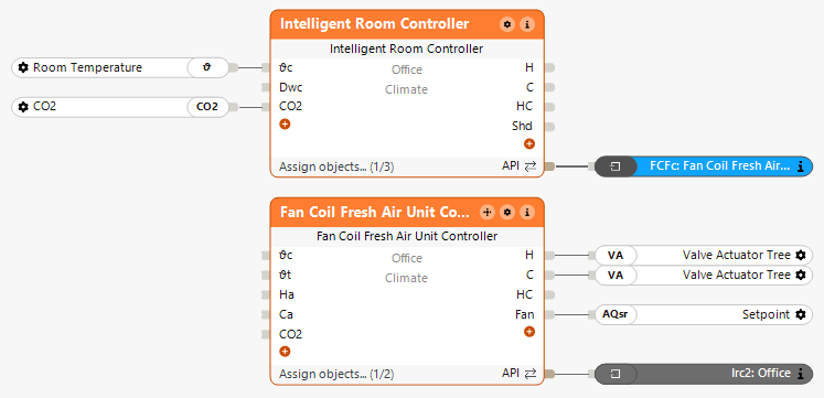
Combination with Intelligent Room Controller
The heating and cooling valves as well as the fan are connected to the corresponding outputs of the block.
The Fan Coil Fresh Air Unit Controller can be connected to the Intelligent Room Controller via the API Connector:
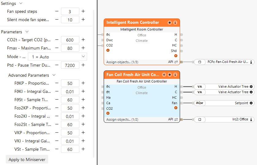
In the properties window, the PI controller parameters for the temperature-based fan regulation, CO2-based fan regulation, and temperature-based valve regulation can be adjusted.
Since this example uses a 4-pipe system, the inputs (Ha) and (Ca) do not need to be connected, as heating and cooling are assumed to be available by default.
The Intelligent Room Controller handles the room logic and passes temperature values and heating/cooling requirements to the Fan Coil Fresh Air Unit Controller.
This adjusts the air volume and heating/cooling valves while considering air quality.
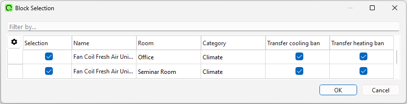
Combination with Intelligent Room Controller and Fan Coil Central Controller
By double-clicking the central block, the corresponding Fan Coil Fresh Air Unit Controllers can be added:
In the properties window, the system type (2-pipe or 4-pipe) can be selected directly:
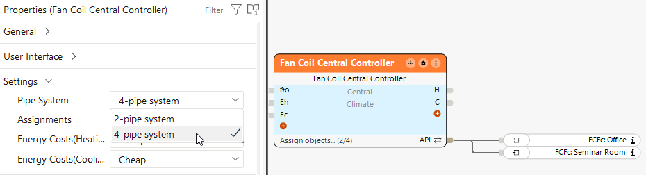
The Fan Coil Central Controller gathers the demands and decides between heating and cooling.
Based on this decision, the Fan Coil Fresh Air Unit Controllers adjust the valves and air volume in the respective rooms, considering air quality.
This block can also operate standalone. In this case, temperature values and CO2 levels are passed directly to the block via the inputs.